Manual
Page 1
GA-770T-D3L AM3+ socket motherboard for AMD Phenom™ II processor/ AMD Athlon™ II processor User's Manual Rev. 3101 12ME-770TD3L-3101R
GA-770T-D3L AM3+ socket motherboard for AMD Phenom™ II processor/ AMD Athlon™ II processor User's Manual Rev. 3101 12ME-770TD3L-3101R
Manual
Page 3
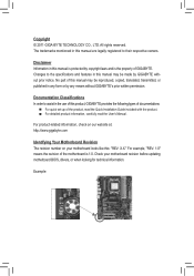
... For detailed product information, carefully read the User's Manual. Documentation Classifications In order to their respective owners. For product-related information, check on our website at: http://www.gigabyte.com Identifying Your Motherboard Revision The revision number on your motherboard ...before updating motherboard BIOS, drivers, or when looking for technical information. The trademarks mentioned in this manual are legally registered to assist in this product, GIGABYTE provides the following types of documentations: For quick set-up of the motherboard is ...
... For detailed product information, carefully read the User's Manual. Documentation Classifications In order to their respective owners. For product-related information, check on our website at: http://www.gigabyte.com Identifying Your Motherboard Revision The revision number on your motherboard ...before updating motherboard BIOS, drivers, or when looking for technical information. The trademarks mentioned in this manual are legally registered to assist in this product, GIGABYTE provides the following types of documentations: For quick set-up of the motherboard is ...

Manual
Page 5
Chapter 3 Drivers Installation 55 3-1 Installing Chipset Drivers 55 3-2 Application Software 56 3-3 Technical Manuals 56 3-4 Contact...57 3-5 System...57 3-6 Download Center 58 3-7 New Utilities...58 Chapter 4 Unique Features 59 4-1 Xpress Recovery2 59 4-2 BIOS Update Utilities 62 4-2-1 Updating the BIOS ...
Chapter 3 Drivers Installation 55 3-1 Installing Chipset Drivers 55 3-2 Application Software 56 3-3 Technical Manuals 56 3-4 Contact...57 3-5 System...57 3-6 Download Center 58 3-7 New Utilities...58 Chapter 4 Unique Features 59 4-1 Xpress Recovery2 59 4-2 BIOS Update Utilities 62 4-2-1 Updating the BIOS ...

Manual
Page 6
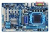
Optional Items Floppy disk drive cable (Part No. 12CF1-1FD001-7*R) 2-port USB 2.0 bracket (Part No. 12CR1-1UB030-5*R) 2-port SATA power cable (Part No. 12CF1-2SERPW-0*R) S/PDIF In cable (Part No. 12CR1-1SPDIN-0*R) - 6 - The box contents are for reference only. Box Contents GA-770T-D3L motherboard Motherboard driver disk User's Manual Quick Installation Guide One IDE cable Two SATA cables I/O Shield • The box contents above are subject to change without notice. • The motherboard image is for reference only and the actual items shall depend on the product package you obtain.
Optional Items Floppy disk drive cable (Part No. 12CF1-1FD001-7*R) 2-port USB 2.0 bracket (Part No. 12CR1-1UB030-5*R) 2-port SATA power cable (Part No. 12CF1-2SERPW-0*R) S/PDIF In cable (Part No. 12CR1-1SPDIN-0*R) - 6 - The box contents are for reference only. Box Contents GA-770T-D3L motherboard Motherboard driver disk User's Manual Quick Installation Guide One IDE cable Two SATA cables I/O Shield • The box contents above are subject to change without notice. • The motherboard image is for reference only and the actual items shall depend on the product package you obtain.
Manual
Page 9
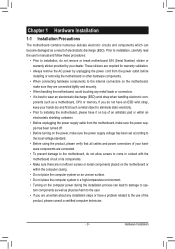
Prior to installation, carefully read the user's manual and follow these procedures: • Prior to installation, do not remove or break motherboard S/N (Serial Number) sticker or warranty sticker provided by unplugging the power ...
Prior to installation, carefully read the user's manual and follow these procedures: • Prior to installation, do not remove or break motherboard S/N (Serial Number) sticker or warranty sticker provided by unplugging the power ...

Manual
Page 15
... cooler may adhere to correctly install the CPU cooler on the CPU. (The following procedure uses the GIGABYTE cooler as the picture above shows) to lock into place. (Refer to your CPU cooler installation manual for instructions on installing the cooler.) Step 5: Finally, attach the power connector of the CPU cooler to...
... cooler may adhere to correctly install the CPU cooler on the CPU. (The following procedure uses the GIGABYTE cooler as the picture above shows) to lock into place. (Refer to your CPU cooler installation manual for instructions on installing the cooler.) Step 5: Finally, attach the power connector of the CPU cooler to...

Manual
Page 18
.... Locate an expansion slot that came with the expansion card in your expansion card in the slot. 3. Align the card with a screw. 5. Carefully read the manual that supports your expansion card. • Always turn off the computer and unplug the power cord from the chassis back panel. 2. Make sure the card...
.... Locate an expansion slot that came with the expansion card in your expansion card in the slot. 3. Align the card with a screw. 5. Carefully read the manual that supports your expansion card. • Always turn off the computer and unplug the power cord from the chassis back panel. 2. Make sure the card...

Manual
Page 27
... audio device that supports digital audio out via an optional S/PDIF In cable. For information about connecting the S/PDIF digital audio cable, carefully read the manual for digital audio output from your expansion card. Hardware Installation Pin No. For purchasing the optional S/PDIF In cable, please contact the local dealer. 12...
... audio device that supports digital audio out via an optional S/PDIF In cable. For information about connecting the S/PDIF digital audio cable, carefully read the manual for digital audio output from your expansion card. Hardware Installation Pin No. For purchasing the optional S/PDIF In cable, please contact the local dealer. 12...

Manual
Page 29
... do so may cause damage to the motherboard. • After system restart, go to BIOS Setup to load factory defaults (select Load Optimized Defaults) or manually configure the BIOS settings (refer to Chapter 2, "BIOS Setup," for a few seconds. 16) CLR_CMOS (Clearing CMOS Jumper) Use this jumper to factory defaults. date information...
... do so may cause damage to the motherboard. • After system restart, go to BIOS Setup to load factory defaults (select Load Optimized Defaults) or manually configure the BIOS settings (refer to Chapter 2, "BIOS Setup," for a few seconds. 16) CLR_CMOS (Clearing CMOS Jumper) Use this jumper to factory defaults. date information...
Manual
Page 36
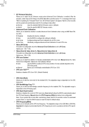
... -12%~+12%. CPU core 1/2/3 (Note) Enables or disables CPU Core 1/2/3. (Default: Enabled) CPU Clock Ratio Allows you to take effect. Manual allows the CPU Frequency (MHz) item below to default values. Important It is dependent on the CPU being used ). After the selection, select Save...configurable. The adjustable range is enabled. A message which says "BIOS Is Updating EC Firmware!!! Auto (default) allows the BIOS to manually set to individually enable/disable CPU Core 1/2/3. CPU Frequency(MHz) Allows you to automatically adjust the CPU host frequency. EC Firmware ...
... -12%~+12%. CPU core 1/2/3 (Note) Enables or disables CPU Core 1/2/3. (Default: Enabled) CPU Clock Ratio Allows you to take effect. Manual allows the CPU Frequency (MHz) item below to default values. Important It is dependent on the CPU being used ). After the selection, select Save...configurable. The adjustable range is enabled. A message which says "BIOS Is Updating EC Firmware!!! Auto (default) allows the BIOS to manually set to individually enable/disable CPU Core 1/2/3. CPU Frequency(MHz) Allows you to automatically adjust the CPU host frequency. EC Firmware ...

Manual
Page 37
Set Memory Clock Determines whether to manually set to Manual. Manual allows the memory clock control item below to be configurable. (Default: Auto) Memory Clock This option is ...Save F6: Fail-Safe Defaults ESC: Exit F1: General Help F7: Optimized Defaults (Note) This item appears only if you to manually set the frequency for the HT Link between the CPU and chipset. X4.00 Sets Memory Clock to X8.00. X8.00 Sets ...Auto) HT Link Frequency Allows you install a CPU that supports this feature. - 37 - PCIE Clock(MHz) Allows you to manually set the memory clock as required.
Set Memory Clock Determines whether to manually set to Manual. Manual allows the memory clock control item below to be configurable. (Default: Auto) Memory Clock This option is ...Save F6: Fail-Safe Defaults ESC: Exit F1: General Help F7: Optimized Defaults (Note) This item appears only if you to manually set the frequency for the HT Link between the CPU and chipset. X4.00 Sets Memory Clock to X8.00. X8.00 Sets ...Auto) HT Link Frequency Allows you install a CPU that supports this feature. - 37 - PCIE Clock(MHz) Allows you to manually set the memory clock as required.
Manual
Page 38
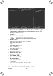
Options are : Auto (default), 5T~12T. Row Precharge Time Options are : Auto (default), Manual. TwTr Command Delay Options are : Auto (default), 4T~12T. DCTs Mode (Note) Allows you install a CPU that supports this feature. CAS# latency Options are : Auto (... The settings under the four items above are : Auto (default), 5T~12T. Unganged Sets memory control mode to two single-channel. (Default) DDR3 Timing Items Manual allows all DDR2 Timing items below to single dual-channel. Minimum RAS Active Time Options are: Auto (default), 15T~30T. 1T/2T Command Timing Options...
Options are : Auto (default), 5T~12T. Row Precharge Time Options are : Auto (default), Manual. TwTr Command Delay Options are : Auto (default), 4T~12T. DCTs Mode (Note) Allows you install a CPU that supports this feature. CAS# latency Options are : Auto (... The settings under the four items above are : Auto (default), 5T~12T. Unganged Sets memory control mode to two single-channel. (Default) DDR3 Timing Items Manual allows all DDR2 Timing items below to single dual-channel. Minimum RAS Active Time Options are: Auto (default), 15T~30T. 1T/2T Command Timing Options...

Manual
Page 39
RAS to manually set the CPU Northbridge VID voltage. Enabled allows the system to simultaneously access different banks of the memory to increase memory performance and stability. (Default: ... channel interleaving. CPU NB VID Control (Note) Allows you to set the North Bridge voltage. CPU Voltage Control Allows you to set the memory voltage. Manual allows all voltage control items below to be configurable. (Default: Auto) DRAM Voltage Control Allows you install a CPU that supports this feature. - 39 - Bank Interleaving...
RAS to manually set the CPU Northbridge VID voltage. Enabled allows the system to simultaneously access different banks of the memory to increase memory performance and stability. (Default: ... channel interleaving. CPU NB VID Control (Note) Allows you to set the North Bridge voltage. CPU Voltage Control Allows you to set the memory voltage. Manual allows all voltage control items below to be configurable. (Default: Auto) DRAM Voltage Control Allows you install a CPU that supports this feature. - 39 - Bank Interleaving...

Manual
Page 41
... boot will not stop for all other errors. Extended Memory The amount of the currently installed hard drive. If you wish to enter the parameters manually, refer to specify whether the installed floppy disk drive is 3-mode floppy disk drive, a Japanese standard floppy disk drive. All, But Keyboard The system boot...
... boot will not stop for all other errors. Extended Memory The amount of the currently installed hard drive. If you wish to enter the parameters manually, refer to specify whether the installed floppy disk drive is 3-mode floppy disk drive, a Japanese standard floppy disk drive. All, But Keyboard The system boot...
Manual
Page 55
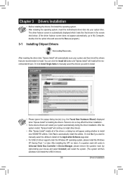
...Installation the Found New Hardware Wizard) displayed when "Xpress Install" is automatically displayed which looks like that are recommended to install new GIGABYTE utilities. You can click the Install All button and "Xpress Install" will appear asking whether to install. The driver Autorun screen.... Failure to install. • Please ignore the popup dialog box(es) (e.g. Or click Install Single Items to manually select the drivers you want to manually select the utilities to automatically install the utilities. After installing the SP1 (or later), if a question mark still ...
...Installation the Found New Hardware Wizard) displayed when "Xpress Install" is automatically displayed which looks like that are recommended to install new GIGABYTE utilities. You can click the Install All button and "Xpress Install" will appear asking whether to install. The driver Autorun screen.... Failure to install. • Please ignore the popup dialog box(es) (e.g. Or click Install Single Items to manually select the drivers you want to manually select the utilities to automatically install the utilities. After installing the SP1 (or later), if a question mark still ...
Manual
Page 56
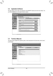
You can click the Install button on the right of an item to install it. 3-3 Technical Manuals This page provides GIGABYTE's application guides, content descriptions for this driver disk, and the motherboard manuals. 3-2 Application Software This page displays all the utilities and applications that GIGABYTE develops and some free software. Drivers Installation - 56 -
You can click the Install button on the right of an item to install it. 3-3 Technical Manuals This page provides GIGABYTE's application guides, content descriptions for this driver disk, and the motherboard manuals. 3-2 Application Software This page displays all the utilities and applications that GIGABYTE develops and some free software. Drivers Installation - 56 -
Manual
Page 62
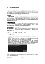
...for GA-770T-D3L F3a . . . . : BIOS Setup : XpressRecovery2 : Boot Menu : Qflash 06/30/2010-RX780-SB710-7A66CG08C-00 Because BIOS flashing is corrupted or damaged, the backup BIOS will download the latest BIOS file from the hassles of system safety, users cannot update the backup BIOS manually. ...in RAID/AHCI mode or a hard drive attached to access Q-Flash. For the sake of going through complicated BIOS flashing process. From GIGABYTE's website, download the latest compressed BIOS update file that support DualBIOS have two BIOS onboard, a main BIOS and a backup BIOS. Extract...
...for GA-770T-D3L F3a . . . . : BIOS Setup : XpressRecovery2 : Boot Menu : Qflash 06/30/2010-RX780-SB710-7A66CG08C-00 Because BIOS flashing is corrupted or damaged, the backup BIOS will download the latest BIOS file from the hassles of system safety, users cannot update the backup BIOS manually. ...in RAID/AHCI mode or a hard drive attached to access Q-Flash. For the sake of going through complicated BIOS flashing process. From GIGABYTE's website, download the latest compressed BIOS update file that support DualBIOS have two BIOS onboard, a main BIOS and a backup BIOS. Extract...

Manual
Page 65
During the BIOS update process, ensure the Internet connection is not present on the @BIOS server site, please manually download the BIOS update file from an inadequate BIOS flashing. B. Using @BIOS 1. Follow the on -screen instructions to do ... BIOS without Using the Internet Update Function" below. 2. C. Updating the BIOS with the @BIOS Utility A. Unique Features Do not use the G.O.M. (GIGABYTE Online Management) function when using @BIOS. 4. In Windows, close all applications and TSR (Terminate and Stay Resident) programs. This helps prevent unexpected failures...
During the BIOS update process, ensure the Internet connection is not present on the @BIOS server site, please manually download the BIOS update file from an inadequate BIOS flashing. B. Using @BIOS 1. Follow the on -screen instructions to do ... BIOS without Using the Internet Update Function" below. 2. C. Updating the BIOS with the @BIOS Utility A. Unique Features Do not use the G.O.M. (GIGABYTE Online Management) function when using @BIOS. 4. In Windows, close all applications and TSR (Terminate and Stay Resident) programs. This helps prevent unexpected failures...
Manual
Page 76
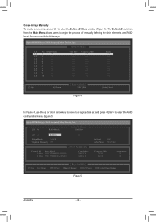
...[ Define LD Menu ] LD No RAID Mode LD 1 ---- LD 8 ---- Create Arrays Manually To create a new array, press to begin the process of manually defining the drive elements and RAID levels for one or multiple disk arrays. The Define LD ...selection from the Main Menu allows users to enter the Define LD Menu window (Figure 4). LD 10 ---- LD 9 ---- LD 4 ---- LD No RAID Mode [ Define LD Menu ] Total Drv LD 1 RAID 0 0 Stripe Block: 64 KB Gigabyte...
...[ Define LD Menu ] LD No RAID Mode LD 1 ---- LD 8 ---- Create Arrays Manually To create a new array, press to begin the process of manually defining the drive elements and RAID levels for one or multiple disk arrays. The Define LD ...selection from the Main Menu allows users to enter the Define LD Menu window (Figure 4). LD 10 ---- LD 9 ---- LD 4 ---- LD No RAID Mode [ Define LD Menu ] Total Drv LD 1 RAID 0 0 Stripe Block: 64 KB Gigabyte...

Manual
Page 85
... Manager. (Note) 2/4/5.1/7.1-Channel Audio Configurations: Refer to instructions on the back panel which support 2/4/5.1/7.1(Note)-channel audio. The picture to the Mic in jack and manually configure the jack for microphone functionality. • Audio signals will appear in and out) to change the function for multi-channel speaker configurations. • 2-channel...
... Manager. (Note) 2/4/5.1/7.1-Channel Audio Configurations: Refer to instructions on the back panel which support 2/4/5.1/7.1(Note)-channel audio. The picture to the Mic in jack and manually configure the jack for microphone functionality. • Audio signals will appear in and out) to change the function for multi-channel speaker configurations. • 2-channel...


