
Manual
Page 1
...ESC: Exit F1: General Help F7: Optimized Defaults The BIOS Setup menus described here may differ from the exact settings for storing your motherboard. Launching the Intel Rapid Storage Technology utility to enable the Intel Smart Response Technology • The Intel Smart Response Technology requires a ...computer system with an Intel Z68 Chipset-based motherboard and an Intel Core series CPU. • The operating system must be installed to enter BIOS Setup during the POST (Power-On ...
...ESC: Exit F1: General Help F7: Optimized Defaults The BIOS Setup menus described here may differ from the exact settings for storing your motherboard. Launching the Intel Rapid Storage Technology utility to enable the Intel Smart Response Technology • The Intel Smart Response Technology requires a ...computer system with an Intel Z68 Chipset-based motherboard and an Intel Core series CPU. • The operating system must be installed to enter BIOS Setup during the POST (Power-On ...

Manual
Page 2
... Intel Rapid Storage Technology utility. - 2 - Installing the operating system and drivers to the SATA disk: After setting the BIOS, you can begin to install all motherboard drivers, including the Intel Rapid Storage Technology driver. After the installation is 10.5 or above and restarting your system, find the IRST icon in...: Step 1: After completing the steps above . 4. English 3. Make sure the Intel Rapid Storage Technology driver version is complete, use the "Xpress Install" function of the motherboard driver disk to install the operating system.
... Intel Rapid Storage Technology utility. - 2 - Installing the operating system and drivers to the SATA disk: After setting the BIOS, you can begin to install all motherboard drivers, including the Intel Rapid Storage Technology driver. After the installation is 10.5 or above and restarting your system, find the IRST icon in...: Step 1: After completing the steps above . 4. English 3. Make sure the Intel Rapid Storage Technology driver version is complete, use the "Xpress Install" function of the motherboard driver disk to install the operating system.
Manual
Page 2
Motherboard G1.Sniper 2 Jul. 8, 2011 Motherboard G1.Sniper 2 Jul. 8, 2011
Motherboard G1.Sniper 2 Jul. 8, 2011 Motherboard G1.Sniper 2 Jul. 8, 2011
Manual
Page 3
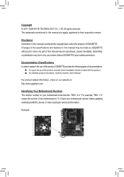
...may be made by any means without prior notice. Example: No part of GIGABYTE. Changes to their respective owners. For example, "REV: 1.0" means the revision of the motherboard is the property of this manual may be reproduced, copied, translated, transmitted,... features in any form or by GIGABYTE without GIGABYTE's prior written permission. For product-related information, check on our website at: http://www.gigabyte.com Identifying Your Motherboard Revision The revision number on your motherboard revision before updating motherboard BIOS, drivers, or when looking for...
...may be made by any means without prior notice. Example: No part of GIGABYTE. Changes to their respective owners. For example, "REV: 1.0" means the revision of the motherboard is the property of this manual may be reproduced, copied, translated, transmitted,... features in any form or by GIGABYTE without GIGABYTE's prior written permission. For product-related information, check on our website at: http://www.gigabyte.com Identifying Your Motherboard Revision The revision number on your motherboard revision before updating motherboard BIOS, drivers, or when looking for...
Manual
Page 4
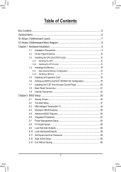
Table of Contents Box Contents...6 Optional Items...6 G1.Sniper 2 Motherboard Layout 7 G1.Sniper 2 Motherboard Block Diagram 8 Chapter 1 Hardware Installation 9 1-1 Installation Precautions 9 1-2 Product Specifications 10 1-3 Installing the CPU and CPU Cooler 13 1-3-1 Installing the CPU 13 1-3-2 Installing the CPU Cooler ...
Table of Contents Box Contents...6 Optional Items...6 G1.Sniper 2 Motherboard Layout 7 G1.Sniper 2 Motherboard Block Diagram 8 Chapter 1 Hardware Installation 9 1-1 Installation Precautions 9 1-2 Product Specifications 10 1-3 Installing the CPU and CPU Cooler 13 1-3-1 Installing the CPU 13 1-3-2 Installing the CPU Cooler ...
Manual
Page 6
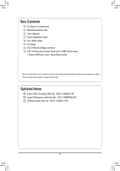
... 2-port USB 2.0 bracket (Part No. 12CR1-1UB030-5*R) 2-port SATA power cable (Part No. 12CF1-2SERPW-0*R) COM port cable (Part No. 12CF1-1CM001-3*R) - 6 - Box Contents G1.Sniper 2 motherboard Motherboard driver disk User's Manual Quick Installation Guide Four SATA cables I/O Shield One 2-Way SLI bridge connector 5.25" Front Access Control Panel with 2 USB 3.0/2.0 ports, 1 Power...
... 2-port USB 2.0 bracket (Part No. 12CR1-1UB030-5*R) 2-port SATA power cable (Part No. 12CF1-2SERPW-0*R) COM port cable (Part No. 12CF1-1CM001-3*R) - 6 - Box Contents G1.Sniper 2 motherboard Motherboard driver disk User's Manual Quick Installation Guide Four SATA cables I/O Shield One 2-Way SLI bridge connector 5.25" Front Access Control Panel with 2 USB 3.0/2.0 ports, 1 Power...
Manual
Page 7
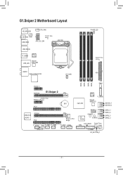
... Marvell USB_LAN 88E1118R AUDIO BigFoot Killer E2100 HP_PWR PHASE LED System4 Temp. sensor FAN3 F_PANEL OC_BUTTON_F - 7 - sensor ATX DDR3_4 DDR3_2 DDR3_3 DDR3_1 PCIEX1_1 FAN4 PCIEX16 G1.Sniper 2 System2 Temp. G1.Sniper 2 Motherboard Layout KB_MS_USB CPU_FAN OC_BUTTON FAN1 USB_HDMI System1 Temp.
... Marvell USB_LAN 88E1118R AUDIO BigFoot Killer E2100 HP_PWR PHASE LED System4 Temp. sensor FAN3 F_PANEL OC_BUTTON_F - 7 - sensor ATX DDR3_4 DDR3_2 DDR3_3 DDR3_1 PCIEX1_1 FAN4 PCIEX16 G1.Sniper 2 System2 Temp. G1.Sniper 2 Motherboard Layout KB_MS_USB CPU_FAN OC_BUTTON FAN1 USB_HDMI System1 Temp.
Manual
Page 8
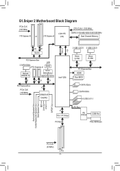
G1.Sniper 2 Motherboard Block Diagram PCIe CLK (100 MHz) 1 PCI Express x16 or 2 PCI Express x8 LGA1155 CPU CPU CLK+/- (100 MHz) DDR3 2133/1866/1600/1333/1066 ...
G1.Sniper 2 Motherboard Block Diagram PCIe CLK (100 MHz) 1 PCI Express x16 or 2 PCI Express x8 LGA1155 CPU CPU CLK+/- (100 MHz) DDR3 2133/1866/1600/1333/1066 ...
Manual
Page 9
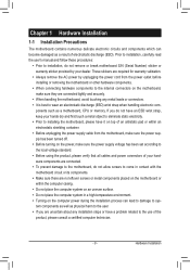
... shielding container. •• Before unplugging the power supply cable from the power outlet before installing or removing the motherboard or other hardware components. •• When connecting hardware components to the internal connectors on the computer power during... the installation process can become damaged as a motherboard, CPU or memory. ponents such as a result of the product, please consult a certified computer technician. - 9 - Hardware Installation ...
... shielding container. •• Before unplugging the power supply cable from the power outlet before installing or removing the motherboard or other hardware components. •• When connecting hardware components to the internal connectors on the computer power during... the installation process can become damaged as a motherboard, CPU or memory. ponents such as a result of the product, please consult a certified computer technician. - 9 - Hardware Installation ...
Manual
Page 12
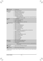
...;Š Support for Xpress Install ŠŠ Support for Xpress Recovery2 ŠŠ Support for EasyTune * Available functions in EasyTune may differ by motherboard model. ŠŠ Support for Dynamic Energy Saver™ 2 ŠŠ Support for Smart 6™ ŠŠ Support for Auto Green...ŠŠ Support for Microsoft® Windows 7/Vista/XP Form Factor ŠŠ ATX Form Factor; 30.5cm x 26.4cm * GIGABYTE reserves the right to make any changes to the integrated graphics port on the CPU/system cooler you install. Operating System ŠŠ Support...
...;Š Support for Xpress Install ŠŠ Support for Xpress Recovery2 ŠŠ Support for EasyTune * Available functions in EasyTune may differ by motherboard model. ŠŠ Support for Dynamic Energy Saver™ 2 ŠŠ Support for Smart 6™ ŠŠ Support for Auto Green...ŠŠ Support for Microsoft® Windows 7/Vista/XP Form Factor ŠŠ ATX Form Factor; 30.5cm x 26.4cm * GIGABYTE reserves the right to make any changes to the integrated graphics port on the CPU/system cooler you install. Operating System ŠŠ Support...
Manual
Page 13
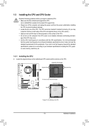
... do so according to your hardware specifications including the CPU, graphics card, memory, hard drive, etc. 1-3-1 Installing the CPU A. Locate the alignment keys on the motherboard CPU socket and the notches on the CPU - 13 - If you may occur. •• Set the CPU host frequency in accordance with the CPU... the standard requirements for the latest CPU support list.) •• Always turn on the computer if the CPU cooler is not recommended that the motherboard supports the CPU. (Go to GIGABYTE's website for the peripherals. Hardware Installation
... do so according to your hardware specifications including the CPU, graphics card, memory, hard drive, etc. 1-3-1 Installing the CPU A. Locate the alignment keys on the motherboard CPU socket and the notches on the CPU - 13 - If you may occur. •• Set the CPU host frequency in accordance with the CPU... the standard requirements for the latest CPU support list.) •• Always turn on the computer if the CPU cooler is not recommended that the motherboard supports the CPU. (Go to GIGABYTE's website for the peripherals. Hardware Installation
Manual
Page 14
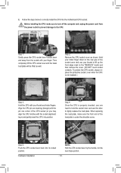
... CPU is under the shoulder screw. When replacing the load plate, make sure to the CPU. Step 5: Push the CPU socket lever back into the motherboard CPU socket. Hardware Installation - 14 - Follow the steps below to hold the socket lever and use your thumb and index fingers. Step 2: Remove the CPU...
... CPU is under the shoulder screw. When replacing the load plate, make sure to the CPU. Step 5: Push the CPU socket lever back into the motherboard CPU socket. Hardware Installation - 14 - Follow the steps below to hold the socket lever and use your thumb and index fingers. Step 2: Remove the CPU...
Manual
Page 15
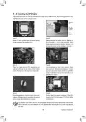
... an even and thin layer of thermal grease on the surface of the installed CPU. Step 6: Finally, attach the power connector of the motherboard. Inadequately removing the CPU cooler may adhere to the CPU. Check that the Male and Female push pins are joined closely. (Refer to ...your CPU cooler installation manual for instructions on the motherboard. 1-3-2 Installing the CPU Cooler Follow the steps below to correctly install the CPU cooler on the motherboard. (The following procedure uses Intel® boxed cooler as the picture above shows, the...
... an even and thin layer of thermal grease on the surface of the installed CPU. Step 6: Finally, attach the power connector of the motherboard. Inadequately removing the CPU cooler may adhere to the CPU. Check that the Male and Female push pins are joined closely. (Refer to ...your CPU cooler installation manual for instructions on the motherboard. 1-3-2 Installing the CPU Cooler Follow the steps below to correctly install the CPU cooler on the motherboard. (The following procedure uses Intel® boxed cooler as the picture above shows, the...
Manual
Page 16
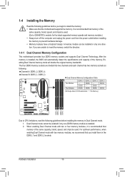
... direction. The four DDR3 memory sockets are unable to insert the memory, switch the direction. 1-4-1 Dual Channel Memory Configuration This motherboard provides four DDR3 memory sockets and supports Dual Channel Technology. Dual Channel mode cannot be installed in only one DDR3 memory module... guidelines before installing the memory to prevent hardware damage. •• Memory modules have a foolproof design. If you begin to GIGABYTE's website for the latest supported memory speeds and memory modules.) •• Always turn off the computer and unplug the power ...
... direction. The four DDR3 memory sockets are unable to insert the memory, switch the direction. 1-4-1 Dual Channel Memory Configuration This motherboard provides four DDR3 memory sockets and supports Dual Channel Technology. Dual Channel mode cannot be installed in only one DDR3 memory module... guidelines before installing the memory to prevent hardware damage. •• Memory modules have a foolproof design. If you begin to GIGABYTE's website for the latest supported memory speeds and memory modules.) •• Always turn off the computer and unplug the power ...
Manual
Page 17
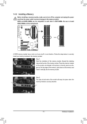
... the picture on the memory and insert it vertically into place when the memory module is securely inserted. - 17 - Place the memory module on this motherboard. DDR3 and DDR2 DIMMs are not compatible to each other or DDR DIMMs. Be sure to install DDR3 DIMMs on the socket. Spread the retaining...
... the picture on the memory and insert it vertically into place when the memory module is securely inserted. - 17 - Place the memory module on this motherboard. DDR3 and DDR2 DIMMs are not compatible to each other or DDR DIMMs. Be sure to install DDR3 DIMMs on the socket. Spread the retaining...
Manual
Page 18
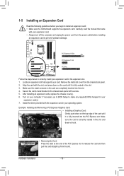
... the card and then pull the card straight up from the power outlet before you begin to install an expansion card: • Make sure the motherboard supports the expansion card. PCI Express x16 Slot PCI Express x1 Slot PCI Slot Follow the steps below to correctly install your expansion card in...
... the card and then pull the card straight up from the power outlet before you begin to install an expansion card: • Make sure the motherboard supports the expansion card. PCI Express x16 Slot PCI Express x1 Slot PCI Slot Follow the steps below to correctly install your expansion card in...
Manual
Page 19
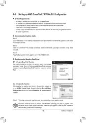
... After installing the graphics card driver in "1-5 Installing an Expansion Card" and install two CrossFireX/SLI graphics cards on your graphics cards. A CrossFireX/SLI-supported motherboard with your graphics cards for enabling CrossFireX/SLI technology may be needed or not depending on the PCI Express x16 slots. To Enable SLI Function...
... After installing the graphics card driver in "1-5 Installing an Expansion Card" and install two CrossFireX/SLI graphics cards on your graphics cards. A CrossFireX/SLI-supported motherboard with your graphics cards for enabling CrossFireX/SLI technology may be needed or not depending on the PCI Express x16 slots. To Enable SLI Function...
Manual
Page 20
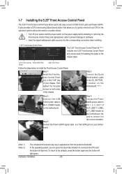
...and screws used for fastening the panel to the chassis sides. Step 2: Connect the Quick Boost button's cable to the OC_BUTTON_ F header on the motherboard. the F_USB1, F_USB2, or F_USB3 header on your chassis. Be sure to the F_USB30 header Pin 1, 3, 5, and 7 of the chassis. Hardware... Installation - 20 - Connect the Power eSATA signal cable to both sides of on the motherboard. (Note 2) Step 3: Step 4: Connect the USB Connect the Power 3.0/2.0 ports' cable to eSATA power cable to connect it in the operation ...
...and screws used for fastening the panel to the chassis sides. Step 2: Connect the Quick Boost button's cable to the OC_BUTTON_ F header on the motherboard. the F_USB1, F_USB2, or F_USB3 header on your chassis. Be sure to the F_USB30 header Pin 1, 3, 5, and 7 of the chassis. Hardware... Installation - 20 - Connect the Power eSATA signal cable to both sides of on the motherboard. (Note 2) Step 3: Step 4: Connect the USB Connect the Power 3.0/2.0 ports' cable to eSATA power cable to connect it in the operation ...
Manual
Page 21
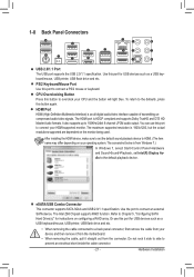
...>Sound>Playback, set the default sound playback device to HDMI. (The item name may differ depending on your device and then remove it from the motherboard. •• When removing the cable, pull it side to side to prevent an electrical short inside the cable connector. - 21 - Do not rock it...
...>Sound>Playback, set the default sound playback device to HDMI. (The item name may differ depending on your device and then remove it from the motherboard. •• When removing the cable, pull it side to side to prevent an electrical short inside the cable connector. - 21 - Do not rock it...
Manual
Page 23
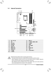
... sure your devices are compliant with the connectors you wish to connect. •• Before installing the devices, be sure to the connector on the motherboard. - 23 - Hardware Installation Unplug the power cord from the power outlet to prevent damage to the devices. •• After installing the device and before...
... sure your devices are compliant with the connectors you wish to connect. •• Before installing the devices, be sure to the connector on the motherboard. - 23 - Hardware Installation Unplug the power cord from the power outlet to prevent damage to the devices. •• After installing the device and before...


