
Manual
Page 9
... have it on top of an antistatic pad or within an electrostatic shielding container. • Before unplugging the power supply cable from the power outlet before installing or removing the motherboard or other hardware components. • When connecting hardware components to the internal...break motherboard S/N (Serial Number) sticker or warranty sticker provided by unplugging the power cord from the motherboard, make sure the power supply has been turned off. • Before turning on the computer power during the installation process can become damaged as a motherboard, CPU or memory....
... have it on top of an antistatic pad or within an electrostatic shielding container. • Before unplugging the power supply cable from the power outlet before installing or removing the motherboard or other hardware components. • When connecting hardware components to the internal...break motherboard S/N (Serial Number) sticker or warranty sticker provided by unplugging the power cord from the motherboard, make sure the power supply has been turned off. • Before turning on the computer power during the installation process can become damaged as a motherboard, CPU or memory....
Manual
Page 19
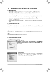
A power supply with two/three/four PCI Express x16 slots and correct driver - C. A CrossFireX/SLI-supported motherboard with sufficient power is selected. CrossFire (Note 1)/SLI bridge connector(s) - Configuring the Graphics Card Driver C-1. Browse to the manual of the graphics cards... PCIEX16_2 slots.) Step 2: Insert the CrossFireX (Note 1)/SLI bridge connectors into the graphics card on top of your graphics cards for the power require ment) B. For 3-Way CrossFireX: After installing the graphics card driver in the operating system, go to the CrossFireX menu and ensure...
A power supply with two/three/four PCI Express x16 slots and correct driver - C. A CrossFireX/SLI-supported motherboard with sufficient power is selected. CrossFire (Note 1)/SLI bridge connector(s) - Configuring the Graphics Card Driver C-1. Browse to the manual of the graphics cards... PCIEX16_2 slots.) Step 2: Insert the CrossFireX (Note 1)/SLI bridge connectors into the graphics card on top of your graphics cards for the power require ment) B. For 3-Way CrossFireX: After installing the graphics card driver in the operating system, go to the CrossFireX menu and ensure...
Manual
Page 20
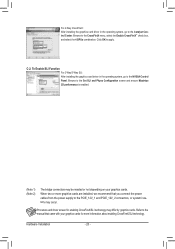
... cards are installed, we recommend that came with your graphics cards. Refer to apply. Click OK to the manual that you connect the power cables from the power supply to the PCIE_12V_1 and PCIE_12V_2 connectors, or system instability may be needed or not depending on your graphics cards for enabling CrossFireX/SLI technology...
... cards are installed, we recommend that came with your graphics cards. Refer to apply. Click OK to the manual that you connect the power cables from the power supply to the PCIE_12V_1 and PCIE_12V_2 connectors, or system instability may be needed or not depending on your graphics cards for enabling CrossFireX/SLI technology...
Manual
Page 21
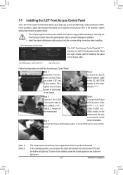
...Boost button to hardware. • Insert the signal cable/power cable securely into a free 5.25" bay of the chassis. USB2 header on the power supply before installing or removing the Front Access Control Panel and signal/power cable to prevent damage to overclock the CPU and the button... products illustrated. Be sure to the defaults, press the button again and the button will light red. Hardware Installation Quick Boost Button Power eSATA Port USB 3.0/2.0 Ports Follow the steps below to install the Front Access Control Panel: Step 1: Install the Front Access Control...
...Boost button to hardware. • Insert the signal cable/power cable securely into a free 5.25" bay of the chassis. USB2 header on the power supply before installing or removing the Front Access Control Panel and signal/power cable to prevent damage to overclock the CPU and the button... products illustrated. Be sure to the defaults, press the button again and the button will light red. Hardware Installation Quick Boost Button Power eSATA Port USB 3.0/2.0 Ports Follow the steps below to install the Front Access Control Panel: Step 1: Install the Front Access Control...

Manual
Page 28
...ATX) Hardware Installation - 28 - The 12V power connector mainly supplies power to the power connector in the correct orientation. Before connecting the power connector, first make sure the power supply is used (500W or greater). If the 12V power connector is not connected, the computer will not...8 4 5 1 ATX_12V_2X/ATX_12V_2X_1 ATX_12V_2X/ATX_12V_2X_1: Pin No. 1/2) ATX_12V_2X/ATX_12V_2X_1/ATX (2x4 12V Power Connectors and 2x12 Main Power Connector) With the use of a power supply providing a 2x4 12V power connector is recommended by +5V) 21 +12V 22 +12V (Only for 2x12-pin ATX)...
...ATX) Hardware Installation - 28 - The 12V power connector mainly supplies power to the power connector in the correct orientation. Before connecting the power connector, first make sure the power supply is used (500W or greater). If the 12V power connector is not connected, the computer will not...8 4 5 1 ATX_12V_2X/ATX_12V_2X_1 ATX_12V_2X/ATX_12V_2X_1: Pin No. 1/2) ATX_12V_2X/ATX_12V_2X_1/ATX (2x4 12V Power Connectors and 2x12 Main Power Connector) With the use of a power supply providing a 2x4 12V power connector is recommended by +5V) 21 +12V 22 +12V (Only for 2x12-pin ATX)...

Manual
Page 29
...Reserve 1 FAN1/FAN2 1 FAN3 • Be sure to connect fan cables to the fan headers to prevent your CPU and system from the power supply to the onboard PCI Express x16 slots. Hardware Installation Most fan headers possess a foolproof insertion design. Definition 1 GND 2 +12V 3 Sense ...4 Speed Control SYS_FAN/FAN1/FAN2/FAN3: Pin No. 3) PCIE_12V_1/PCIE_12V_2 (Power Connectors) The power connectors provide auxiliary power to the PCIE_12V_1 and PCIE_12V_2 connectors, or system instability may hang. • These fan headers are 4-pin and support fan ...
...Reserve 1 FAN1/FAN2 1 FAN3 • Be sure to connect fan cables to the fan headers to prevent your CPU and system from the power supply to the onboard PCI Express x16 slots. Hardware Installation Most fan headers possess a foolproof insertion design. Definition 1 GND 2 +12V 3 Sense ...4 Speed Control SYS_FAN/FAN1/FAN2/FAN3: Pin No. 3) PCIE_12V_1/PCIE_12V_2 (Power Connectors) The power connectors provide auxiliary power to the PCIE_12V_1 and PCIE_12V_2 connectors, or system instability may hang. • These fan headers are 4-pin and support fan ...
Manual
Page 37
... section in this chapter or introductions of the system in the main menu of BIOS, it with caution. For instructions on the motherboard supplies the necessary power to the CMOS to Chapter 4, "BIOS Update Utilities." • Because BIOS flashing is recommended that you not alter the default settings ...on the motherboard. To see more advanced BIOS Setup menu options, you can press + in the CMOS on . To upgrade the BIOS, use either the GIGABYTE Q-Flash or @BIOS utility. • Q-Flash allows the user to clear the CMOS values.) - 37 - Refer to Chapter 5, "Troubleshooting," for ...
... section in this chapter or introductions of the system in the main menu of BIOS, it with caution. For instructions on the motherboard supplies the necessary power to the CMOS to Chapter 4, "BIOS Update Utilities." • Because BIOS flashing is recommended that you not alter the default settings ...on the motherboard. To see more advanced BIOS Setup menu options, you can press + in the CMOS on . To upgrade the BIOS, use either the GIGABYTE Q-Flash or @BIOS utility. • Q-Flash allows the user to clear the CMOS values.) - 37 - Refer to Chapter 5, "Troubleshooting," for ...

Manual
Page 57
...Up Allows the system to be resumed at any time. Note: When using the power button. In S1 sleep state, the system appears suspended and stays in MS-DOS mode using this function, you need an ATX power supply providing at least 1A on the +5VSB lead. (Default: Enabled) Resume by ...Alarm Determines whether to turn off the computer in a low power mode. Soft-Off by PWR-BTTN Configures the way to power on the system at a desired time. (Default: ...
...Up Allows the system to be resumed at any time. Note: When using the power button. In S1 sleep state, the system appears suspended and stays in MS-DOS mode using this function, you need an ATX power supply providing at least 1A on the +5VSB lead. (Default: Enabled) Resume by ...Alarm Determines whether to turn off the computer in a low power mode. Soft-Off by PWR-BTTN Configures the way to power on the system at a desired time. (Default: ...

Manual
Page 58
... or disables High Precision Event Timer (HPET) for Windows 7/Vista operating system. (Default: Enabled) HPET Mode (Note) Allows you need an ATX power supply providing at least 1A on the +5VSB lead. Press on this function, you to turn on the system, enter the password and press . ErP... for the password, press again without entering the password to let the system consume less than 1W power in S5 (shutdown) state. (Default: Disabled) Note: When this item. Note: you need an ATX power supply providing at least 1A on the system. To turn on the +5VSB lead. BIOS Setup -...
... or disables High Precision Event Timer (HPET) for Windows 7/Vista operating system. (Default: Enabled) HPET Mode (Note) Allows you need an ATX power supply providing at least 1A on the +5VSB lead. Press on this function, you to turn on the system, enter the password and press . ErP... for the password, press again without entering the password to let the system consume less than 1W power in S5 (shutdown) state. (Default: Disabled) Note: When this item. Note: you need an ATX power supply providing at least 1A on the system. To turn on the +5VSB lead. BIOS Setup -...
Manual
Page 87
...; Motherboard driver disk. 5-1-1 Configuring Intel ICH10R SATA Controllers A. Installing SATA hard drive(s) in RAID BIOS. (Note 1) D. Appendix Configure a RAID array in your power supply to the hard drive. (Note 1) Skip this step if you use two hard drives with identical model and capacity). If there is recommended that you...is set to available SATA port on this motherboard, the SATA2_0~SATA2_5 ports are supported by the ICH10R South Bridge.) Then connect the power connector from your computer Attach one end of the SATA signal cable to the rear of the SATA hard drive and the other ...
...; Motherboard driver disk. 5-1-1 Configuring Intel ICH10R SATA Controllers A. Installing SATA hard drive(s) in RAID BIOS. (Note 1) D. Appendix Configure a RAID array in your power supply to the hard drive. (Note 1) Skip this step if you use two hard drives with identical model and capacity). If there is recommended that you...is set to available SATA port on this motherboard, the SATA2_0~SATA2_5 ports are supported by the ICH10R South Bridge.) Then connect the power connector from your computer Attach one end of the SATA signal cable to the rear of the SATA hard drive and the other ...

Manual
Page 95
... F7: Optimized Defaults Step 2: Save changes and exit BIOS Setup. 5-1-2 Configuring Marvell 88SE9182 SATA Controller A. Installing SATA hard drive(s) in your power supply to enter BIOS Setup during the POST. B. Configuring SATA controller and RAID mode in this section may differ from your computer Attach one end ...of the SATA hard drive and the other end to configure the SATA controller mode correctly in system BIOS Setup. Then connect the power connector from the exact settings for your computer and press to the hard drive. Step 1: Turn on the motherboard you will see...
... F7: Optimized Defaults Step 2: Save changes and exit BIOS Setup. 5-1-2 Configuring Marvell 88SE9182 SATA Controller A. Installing SATA hard drive(s) in your power supply to enter BIOS Setup during the POST. B. Configuring SATA controller and RAID mode in this section may differ from your computer Attach one end ...of the SATA hard drive and the other end to configure the SATA controller mode correctly in system BIOS Setup. Then connect the power connector from the exact settings for your computer and press to the hard drive. Step 1: Turn on the motherboard you will see...
Manual
Page 117
...installed successfully (check in My Computer > Properties > Gen- For more FAQs for your motherboard, please go to the Support & Downloads\FAQ page on GIGABYTE's website. 5-4 Troubleshooting 5-4-1 Frequently Asked Questions To read more details, go to the Support & Downloads\FAQ page on our website and search for ... still on the computer name and select Scan for hardware changes. You can temporarily remove the battery from the battery holder to stop supplying power to the CMOS, which will clear the CMOS values after the computer shuts down ? Q: What do the beeps emitted during the POST...
...installed successfully (check in My Computer > Properties > Gen- For more FAQs for your motherboard, please go to the Support & Downloads\FAQ page on GIGABYTE's website. 5-4 Troubleshooting 5-4-1 Frequently Asked Questions To read more details, go to the Support & Downloads\FAQ page on our website and search for ... still on the computer name and select Scan for hardware changes. You can temporarily remove the battery from the battery holder to stop supplying power to the CMOS, which will clear the CMOS values after the computer shuts down ? Q: What do the beeps emitted during the POST...

Manual
Page 119
... graphics card, expansion slot, or monitor might fail. Check if the system can boot successfully. Select "Save & Exit Setup" to solve your question. No The power supply, CPU or CPU socket might fail. Yes Check if there is working properly. Yes Reinstall the operating system. The problem is unable to save changes...
... graphics card, expansion slot, or monitor might fail. Check if the system can boot successfully. Select "Save & Exit Setup" to solve your question. No The power supply, CPU or CPU socket might fail. Yes Check if there is working properly. Yes Reinstall the operating system. The problem is unable to save changes...


