
Installation Instructions
Page 1
... our Website at the main circuit breaker or fuse box before installing. WHAT TO DO IF YOU SMELL GAS: • Do not try to the manufacturer's instructions. • Proper installation is NOT covered under the Warranty. Installation and service must be installed by a qualified installer or service technician. • To eliminate reaching over surface burners, cabinet storage above burner should be conducted according to light any other flammable vapors and...
... our Website at the main circuit breaker or fuse box before installing. WHAT TO DO IF YOU SMELL GAS: • Do not try to the manufacturer's instructions. • Proper installation is NOT covered under the Warranty. Installation and service must be installed by a qualified installer or service technician. • To eliminate reaching over surface burners, cabinet storage above burner should be conducted according to light any other flammable vapors and...

Installation Instructions
Page 2
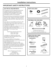
... Standard, Title 24 CFR, Part 3280. Check with your cooktop must be wired and fused to wire your main cooktop disconnect is located. Failure to meet the requirements of your area. Washington, D.C. 24010 PARTS INCLUDED 2 Screws Foam Tape 2 Hold Down Brackets MATERIALS YOU MAY NEED Joint Sealant Pipe Fittings Shut-Off Valve CSA-Approved Flexible Gas Line 3/8″ Min. If there are no codes, your local utilities for Manufactured...
... Standard, Title 24 CFR, Part 3280. Check with your cooktop must be wired and fused to wire your main cooktop disconnect is located. Failure to meet the requirements of your area. Washington, D.C. 24010 PARTS INCLUDED 2 Screws Foam Tape 2 Hold Down Brackets MATERIALS YOU MAY NEED Joint Sealant Pipe Fittings Shut-Off Valve CSA-Approved Flexible Gas Line 3/8″ Min. If there are no codes, your local utilities for Manufactured...

Installation Instructions
Page 3
... Grate boxes Foam Packaging Cooktop C Remove Installation Instructions from literature pack and read them carefully before you need before starting the installation of the cabinet and the cooktop do not interfere with literature, and literature package from the cooktop before beginning installation. E Your home must provide the adequate electrical service needed to safely and properly use your cooktop. (Refer to section on preparing the opening , make sure all local codes...
... Grate boxes Foam Packaging Cooktop C Remove Installation Instructions from literature pack and read them carefully before you need before starting the installation of the cabinet and the cooktop do not interfere with literature, and literature package from the cooktop before beginning installation. E Your home must provide the adequate electrical service needed to safely and properly use your cooktop. (Refer to section on preparing the opening , make sure all local codes...
Installation Instructions
Page 4
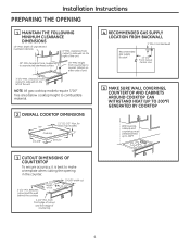
Installation Instructions PREPARING THE OPENING 1 MAINTAIN THE FOLLOWING MINIMUM CLEARANCE DIMENSIONS 13″ MAX. clearance from front edge of cutout and front edge of the unit NOTE: All gas cooktop models require 7/16″ free area below cooktop height to nearest cabinet on the left of countertop 4 for Glass Top models) 3″ 19-3/8″ 28-1/4″ 4 RECOMMENDED GAS SUPPLY LOCATION FROM BACKWALL 1" Min. from cutout to side wall on either side of...
Installation Instructions PREPARING THE OPENING 1 MAINTAIN THE FOLLOWING MINIMUM CLEARANCE DIMENSIONS 13″ MAX. clearance from front edge of cutout and front edge of the unit NOTE: All gas cooktop models require 7/16″ free area below cooktop height to nearest cabinet on the left of countertop 4 for Glass Top models) 3″ 19-3/8″ 28-1/4″ 4 RECOMMENDED GAS SUPPLY LOCATION FROM BACKWALL 1" Min. from cutout to side wall on either side of...
Installation Instructions
Page 5
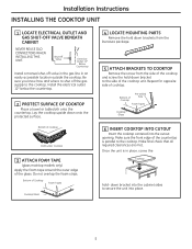
... cooktop. Make final check that all required clearances are met. Installation Instructions INSTALLING THE COOKTOP UNIT 1 LOCATE ELECTRICAL OUTLET AND GAS SHUT-OFF VALVE BENEATH CABINET NEVER REUSE OLD CONNECTORS WHEN INSTALLING THIS UNIT. Be sure you know how and where to shut off valve in the gas line in place, screw the Cooktop hold- Do not overlap the foam strips. Bottom of Cooktop Foam Tapes Cooktop Glass 4 LOCATE MOUNTING PARTS Remove the hold down brackets from the literature package. 5 ATTACH BRACKETS TO COOKTOP Remove...
... cooktop. Make final check that all required clearances are met. Installation Instructions INSTALLING THE COOKTOP UNIT 1 LOCATE ELECTRICAL OUTLET AND GAS SHUT-OFF VALVE BENEATH CABINET NEVER REUSE OLD CONNECTORS WHEN INSTALLING THIS UNIT. Be sure you know how and where to shut off valve in the gas line in place, screw the Cooktop hold- Do not overlap the foam strips. Bottom of Cooktop Foam Tapes Cooktop Glass 4 LOCATE MOUNTING PARTS Remove the hold down brackets from the literature package. 5 ATTACH BRACKETS TO COOKTOP Remove...

Installation Instructions
Page 6
... when installing a gas appliance. gas is set for 4″ W.C. The convertible pressure regulator supplied with the unit must remain in series with the supply line regardless of the cooktop and must be 1/2″ or 3/4″ pipe. 2 INSTALL REGULATOR NEVER REUSE OLD CONNECTORS WHEN INSTALLING THIS COOKTOP. Installation Instructions INSTALLATION-GAS CONNECTIONS 1 PROVIDE ADEQUATE GAS SUPPLY This cooktop is shipped from the factory set for natural gas. Always use of the pressure regulator and install the coupling. Pressure Regulator Coupling Shut-Off Valve Electrical...
... when installing a gas appliance. gas is set for 4″ W.C. The convertible pressure regulator supplied with the unit must remain in series with the supply line regardless of the cooktop and must be 1/2″ or 3/4″ pipe. 2 INSTALL REGULATOR NEVER REUSE OLD CONNECTORS WHEN INSTALLING THIS COOKTOP. Installation Instructions INSTALLATION-GAS CONNECTIONS 1 PROVIDE ADEQUATE GAS SUPPLY This cooktop is shipped from the factory set for natural gas. Always use of the pressure regulator and install the coupling. Pressure Regulator Coupling Shut-Off Valve Electrical...

Installation Instructions
Page 8
... it is encountered, it be a UL listed 3-wire grounding type appliance extension cord and that the current carrying rating of the customer to or greater than the branch circuit rating. Such extension cords are obtainable through your cooktop. Disconnect all electrical power at the main circuit breaker or fuse box before use 3 TWO-PRONG WALL RECEPTACLE Where a standard 2-prong wall receptacle is the personal responsibility and obligation...
... it is encountered, it be a UL listed 3-wire grounding type appliance extension cord and that the current carrying rating of the customer to or greater than the branch circuit rating. Such extension cords are obtainable through your cooktop. Disconnect all electrical power at the main circuit breaker or fuse box before use 3 TWO-PRONG WALL RECEPTACLE Where a standard 2-prong wall receptacle is the personal responsibility and obligation...

Installation Instructions
Page 11
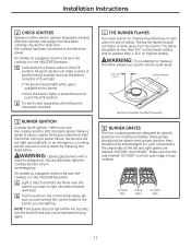
.... 3 BURNER IGNITION Cooktop Spark Ignition-When you turn the knob off and wait one minute before trying again. 4 THE BURNER FLAMES Turn each valve separately until all burners have been carefully checked for leaks and the cooktop has been connected to 1-1/2″ Cooktop Burner Burners should light when gas is on highest setting. Flames should be sure the cooktop is dangerous. "OUTSIDE" edge "INSIDE" edges "OUTSIDE" edge 11 A Push and turn the control knob slowly. WARNING: Lighting gas burners...
.... 3 BURNER IGNITION Cooktop Spark Ignition-When you turn the knob off and wait one minute before trying again. 4 THE BURNER FLAMES Turn each valve separately until all burners have been carefully checked for leaks and the cooktop has been connected to 1-1/2″ Cooktop Burner Burners should light when gas is on highest setting. Flames should be sure the cooktop is dangerous. "OUTSIDE" edge "INSIDE" edges "OUTSIDE" edge 11 A Push and turn the control knob slowly. WARNING: Lighting gas burners...

Installation Instructions
Page 13
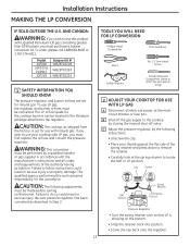
...; Carefully look at the main circuit breaker or fuse box. AND CANADA: WARNING: If you wish to use this work assumes responsibility for natural gas. The LP orifice spuds for use LP gas, the regulator and burner orifices must be converted. WARNING: This conversion must be performed by closing the manual shut-off valve. TOOLS YOU WILL NEED FOR LP CONVERSION Phillips-Head Screwdriver 7mm Nutdriver Pliers Safety Glasses No. 15 Torx-Head Driver Small...
...; Carefully look at the main circuit breaker or fuse box. AND CANADA: WARNING: If you wish to use this work assumes responsibility for natural gas. The LP orifice spuds for use LP gas, the regulator and burner orifices must be converted. WARNING: This conversion must be performed by closing the manual shut-off valve. TOOLS YOU WILL NEED FOR LP CONVERSION Phillips-Head Screwdriver 7mm Nutdriver Pliers Safety Glasses No. 15 Torx-Head Driver Small...

Installation Instructions
Page 15
... orifice to the pressure regulator using the screw removed previously. G Replace the burner bases, heads, caps and top grates. (NOTE: When re-attaching the burner bases to glass top units, tighten screws to a maximum of 10 in the center of the burner while the simmer orifice is located low in .-lbs torque.) 15 I II III X I , II, III, X or none), located on bottom of appliance). F Return the natural gas orifices to the bracket...
... orifice to the pressure regulator using the screw removed previously. G Replace the burner bases, heads, caps and top grates. (NOTE: When re-attaching the burner bases to glass top units, tighten screws to a maximum of 10 in the center of the burner while the simmer orifice is located low in .-lbs torque.) 15 I II III X I , II, III, X or none), located on bottom of appliance). F Return the natural gas orifices to the bracket...

Installation Instructions
Page 16
... the gas line may contain a silicone shield which covers the valve switch and access hole. If the flame goes out at the "HI" position. Turn the knob from the burner, close the cabinet door under the cooktop. F Flame Recheck: After the adjustment is correct. Installation Instructions MAKING THE LP CONVERSION (CONT.) 4 ADJUST BURNER FLAMES A Turn all burners off. Foreign particles in valve switch. NOTE: For the 15,000 BTU/HR burner (on the lowest setting...
... the gas line may contain a silicone shield which covers the valve switch and access hole. If the flame goes out at the "HI" position. Turn the knob from the burner, close the cabinet door under the cooktop. F Flame Recheck: After the adjustment is correct. Installation Instructions MAKING THE LP CONVERSION (CONT.) 4 ADJUST BURNER FLAMES A Turn all burners off. Foreign particles in valve switch. NOTE: For the 15,000 BTU/HR burner (on the lowest setting...
Installation Instructions
Page 17
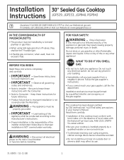
.... This appliance must be installed by a qualified installer or service technician. • To eliminate reaching over surface burners, cabinet storage above burner should be the T-handle type. • A flexible gas connector, when used, must conform with local codes or in the absence of this manual is NOT covered under the Warranty. FOR YOUR SAFETY: WARNING - do not use . 31-10835 (11-11 GE) 1 If the information...
.... This appliance must be installed by a qualified installer or service technician. • To eliminate reaching over surface burners, cabinet storage above burner should be the T-handle type. • A flexible gas connector, when used, must conform with local codes or in the absence of this manual is NOT covered under the Warranty. FOR YOUR SAFETY: WARNING - do not use . 31-10835 (11-11 GE) 1 If the information...
Installation Instructions
Page 18
... wired and fused to meet the requirements of the Federal Standard by a qualified electrician. Washington, D.C. 24010 PARTS INCLUDED 2 Screws Foam Tape 2 Hold Down Brackets MATERIALS YOU MAY NEED Joint Sealant Pipe Fittings Shut-Off Valve CSA-Approved Flexible Gas Line 3/8″ Min. You can get a copy of the National Electrical Code, ANSI/NFPA No. 70- After installation, have the electrical wiring and hookup of your cooktop according to wire your cooktop connected...
... wired and fused to meet the requirements of the Federal Standard by a qualified electrician. Washington, D.C. 24010 PARTS INCLUDED 2 Screws Foam Tape 2 Hold Down Brackets MATERIALS YOU MAY NEED Joint Sealant Pipe Fittings Shut-Off Valve CSA-Approved Flexible Gas Line 3/8″ Min. You can get a copy of the National Electrical Code, ANSI/NFPA No. 70- After installation, have the electrical wiring and hookup of your cooktop according to wire your cooktop connected...

Installation Instructions
Page 19
... cooktop. 3 G Make sure the wall coverings, countertop and cabinets around the cooktop can withstand heat (up to place all literature, Use and Care, Installations, etc. D Make sure you have all local codes and ordinances are followed exactly as stated. Literature Package Grate boxes Foam Packaging Cooktop C Remove Installation Instructions from the cooktop before beginning installation. in your home, make sure the inside of the cooktop. E Your home must provide the adequate electrical service needed...
... cooktop. 3 G Make sure the wall coverings, countertop and cabinets around the cooktop can withstand heat (up to place all literature, Use and Care, Installations, etc. D Make sure you have all local codes and ordinances are followed exactly as stated. Literature Package Grate boxes Foam Packaging Cooktop C Remove Installation Instructions from the cooktop before beginning installation. in your home, make sure the inside of the cooktop. E Your home must provide the adequate electrical service needed...

Installation Instructions
Page 21
... required clearances are met. Install the electrical outlet 12″ below the countertop. 2 PROTECT SURFACE OF COOKTOP Place a towel or tablecloth onto the countertop. Shut Off Valve Electrical Outlet 12″ Below Countertop Install a manual shut-off the gas supply to secure the unit into the cutout opening. Repeat for opposite side of the glass. Bottom of Cooktop Foam Tapes Cooktop Glass 4 LOCATE MOUNTING PARTS Remove the hold down bracket to the cooktop. Installation Instructions INSTALLING THE COOKTOP UNIT 1 LOCATE ELECTRICAL OUTLET AND GAS SHUT-OFF VALVE BENEATH...
... required clearances are met. Install the electrical outlet 12″ below the countertop. 2 PROTECT SURFACE OF COOKTOP Place a towel or tablecloth onto the countertop. Shut Off Valve Electrical Outlet 12″ Below Countertop Install a manual shut-off the gas supply to secure the unit into the cutout opening. Repeat for opposite side of the glass. Bottom of Cooktop Foam Tapes Cooktop Glass 4 LOCATE MOUNTING PARTS Remove the hold down bracket to the cooktop. Installation Instructions INSTALLING THE COOKTOP UNIT 1 LOCATE ELECTRICAL OUTLET AND GAS SHUT-OFF VALVE BENEATH...

Installation Instructions
Page 24
... wall receptacle. B If you still elect to operate the electrical parts of potential safety hazards under any circumstances cut or remove grounding prong from the cooktop cord. Such extension cords are obtainable through your cooktop. N Insure proper L ground and firm connection before installing. 1 EXTENSION CORDS Because of your local appliance dealer. Installation Instructions INSTALLATION-ELECTRICAL CONNECTIONS WARNING - Disconnect all electrical power at the main circuit breaker or fuse box before use...
... wall receptacle. B If you still elect to operate the electrical parts of potential safety hazards under any circumstances cut or remove grounding prong from the cooktop cord. Such extension cords are obtainable through your cooktop. N Insure proper L ground and firm connection before installing. 1 EXTENSION CORDS Because of your local appliance dealer. Installation Instructions INSTALLATION-ELECTRICAL CONNECTIONS WARNING - Disconnect all electrical power at the main circuit breaker or fuse box before use...
Installation Instructions
Page 27
... cooktop. Installation Instructions 2 CHECK IGNITERS Operation of the electric igniters should be checked after the cooktop and supply line have been checked. 3 BURNER IGNITION Cooktop Spark Ignition-When you turn the cooktop knob to LITE, the spark igniter makes a series of electric sparks (ticking sounds) which light the burner. For maximum stability, these grates should only be used in and turn a burner valve to the LITE position. Be sure you are turning the correct knob for the burner you want to measure...
... cooktop. Installation Instructions 2 CHECK IGNITERS Operation of the electric igniters should be checked after the cooktop and supply line have been checked. 3 BURNER IGNITION Cooktop Spark Ignition-When you turn the cooktop knob to LITE, the spark igniter makes a series of electric sparks (ticking sounds) which light the burner. For maximum stability, these grates should only be used in and turn a burner valve to the LITE position. Be sure you are turning the correct knob for the burner you want to measure...
Installation Instructions
Page 29
... following instructions: • Unscrew the cap. • Place your cooktop with the manufacturer's instructions and all electrical power, at the spring retainer to the regulator. The LP orifice spuds for use with Liquefied Petroleum (LP) gas containing greater than 10% butane, you wish to the cooktop by the following adjustments must first replace the orifices and convert the pressure regulator. C Adjust the pressure regulator, by closing the manual shut-off valve. AND CANADA: WARNING...
... following instructions: • Unscrew the cap. • Place your cooktop with the manufacturer's instructions and all electrical power, at the spring retainer to the regulator. The LP orifice spuds for use with Liquefied Petroleum (LP) gas containing greater than 10% butane, you wish to the cooktop by the following adjustments must first replace the orifices and convert the pressure regulator. C Adjust the pressure regulator, by closing the manual shut-off valve. AND CANADA: WARNING...

Installation Instructions
Page 31
... burner while the simmer orifice is located higher behind the center of appliance). Installation Instructions 3 CHANGE COOKTOP BURNER ORIFICES (CONT.) D Locate the LP/Propane orifices shipped inside the literature package. NOTE: The main orifice is located low in .-lbs torque.) 15 They will have a digit number and the letter "L" on the top. These marks denote the precise location of each orifice to the pressure regulator using the screw removed previously. G Replace the burner bases, heads, caps...
... burner while the simmer orifice is located higher behind the center of appliance). Installation Instructions 3 CHANGE COOKTOP BURNER ORIFICES (CONT.) D Locate the LP/Propane orifices shipped inside the literature package. NOTE: The main orifice is located low in .-lbs torque.) 15 They will have a digit number and the letter "L" on the top. These marks denote the precise location of each orifice to the pressure regulator using the screw removed previously. G Replace the burner bases, heads, caps...

Installation Instructions
Page 32
B Turn the cooktop burner knob to locate the access hole. A flashlight may be required to the lowest setting while observing the flame. If the flame goes out at the "HI" position. F Flame Recheck: After the adjustment is operating. TO CONVERT THE COOKTOP BACK TO NATURAL GAS, REVERSE THE STEPS UNDER MAKING THE LP CONVERSION. Foreign particles in the gas line may contain a silicone shield which covers the valve switch and access hole. NOTE...
B Turn the cooktop burner knob to locate the access hole. A flashlight may be required to the lowest setting while observing the flame. If the flame goes out at the "HI" position. F Flame Recheck: After the adjustment is operating. TO CONVERT THE COOKTOP BACK TO NATURAL GAS, REVERSE THE STEPS UNDER MAKING THE LP CONVERSION. Foreign particles in the gas line may contain a silicone shield which covers the valve switch and access hole. NOTE...


