Gateway Quick Start Guide for Windows 7
Page 53
...to reduce the quantity of our products. Mercury advisory For electronic products containing a non-LED-backlit LCD/CRT monitor or display: Lamp(s) inside this program, Gateway will help protect the environment and reduce health hazards. For mor information, contact the Electronic Industries Alliance...This label allows a quick recognition of your energy bill and contribute to reduce carbon dioxide emissions. ENERGY STAR® PARTNERSHIP Gateway is replaced by the US environmental Protection Agency in the dustbin. Energy Star® was introduced by an incorrect type. By joining ...
...to reduce the quantity of our products. Mercury advisory For electronic products containing a non-LED-backlit LCD/CRT monitor or display: Lamp(s) inside this program, Gateway will help protect the environment and reduce health hazards. For mor information, contact the Electronic Industries Alliance...This label allows a quick recognition of your energy bill and contribute to reduce carbon dioxide emissions. ENERGY STAR® PARTNERSHIP Gateway is replaced by the US environmental Protection Agency in the dustbin. Energy Star® was introduced by an incorrect type. By joining ...
Service Guide
Page 4
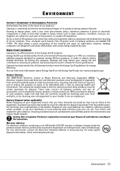
... 62 Replacing the LCD panel assembly 64 Replacing the palm rest 68 Replacing the speakers 72 Replacing the touchpad board 74 Replacing the modem board 77 Replacing the USB board 80 Replacing the Bluetooth module 83 Replacing the system board 86 Replacing the cooling assembly 89 Replacing the processor 92 Replacing the LCD front panel 95 Replacing the webcam 98 Replacing the LCD 100 Replacing the LCD panel...
... 62 Replacing the LCD panel assembly 64 Replacing the palm rest 68 Replacing the speakers 72 Replacing the touchpad board 74 Replacing the modem board 77 Replacing the USB board 80 Replacing the Bluetooth module 83 Replacing the system board 86 Replacing the cooling assembly 89 Replacing the processor 92 Replacing the LCD front panel 95 Replacing the webcam 98 Replacing the LCD 100 Replacing the LCD panel...
Service Guide
Page 5
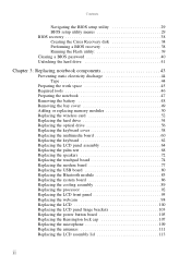
www.gateway.com Chapter 4: Troubleshooting 115 Diagnosing problems 116 System test procedures ... messages 121 No-beep error messages 123 Phoenix BIOS beep codes 124 Symptom-to-FRU error messages 129 LCD 129 Power 129 Memory 130 Sound 130 Power management 130 Devices 131 Keyboard and touchpad 131 Intermittent problems...133 Chapter 5: Connector locations 135 System board layout 136 Top view 136 Bottom view 137 Chapter 6: FRU (Field-Replaceable Unit) list 139 Introduction 140 Exploded diagram 140 FRU list 142 Appendix A: Test compatible components 151 Introduction 152 ...
www.gateway.com Chapter 4: Troubleshooting 115 Diagnosing problems 116 System test procedures ... messages 121 No-beep error messages 123 Phoenix BIOS beep codes 124 Symptom-to-FRU error messages 129 LCD 129 Power 129 Memory 130 Sound 130 Power management 130 Devices 131 Keyboard and touchpad 131 Intermittent problems...133 Chapter 5: Connector locations 135 System board layout 136 Top view 136 Bottom view 137 Chapter 6: FRU (Field-Replaceable Unit) list 139 Introduction 140 Exploded diagram 140 FRU list 142 Appendix A: Test compatible components 151 Introduction 152 ...
Service Guide
Page 49
... • Replacing the LCD panel assembly • Replacing the palm rest • Replacing the speakers • Replacing the touchpad board • Replacing the modem board • Replacing the USB board • Replacing the Bluetooth module • Replacing the system board • Replacing the cooling assembly • Replacing the processor • Replacing the LCD front panel • Replacing the webcam • Replacing the LCD • Replacing the LCD panel...
... • Replacing the LCD panel assembly • Replacing the palm rest • Replacing the speakers • Replacing the touchpad board • Replacing the modem board • Replacing the USB board • Replacing the Bluetooth module • Replacing the system board • Replacing the cooling assembly • Replacing the processor • Replacing the LCD front panel • Replacing the webcam • Replacing the LCD • Replacing the LCD panel...
Service Guide
Page 64
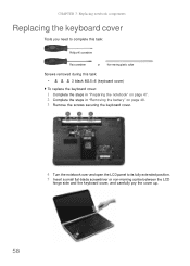
...to complete this task: Phillips #0 screwdriver Flat screwdriver or Non-marring plastic scribe Screws removed during this task: • 3 black M2.5×6 (keyboard cover) To replace the keyboard cover: 1 Complete the steps in "Preparing the notebook" on page 47. 2 Complete the steps in "Removing the battery" on page 48. 3 ...Remove the screws securing the keyboard cover. 4 Turn the notebook over and open the LCD panel to its fully extended position. 5 Insert a small flat-blade screwdriver or non-marring scribe between the...
...to complete this task: Phillips #0 screwdriver Flat screwdriver or Non-marring plastic scribe Screws removed during this task: • 3 black M2.5×6 (keyboard cover) To replace the keyboard cover: 1 Complete the steps in "Preparing the notebook" on page 47. 2 Complete the steps in "Removing the battery" on page 48. 3 ...Remove the screws securing the keyboard cover. 4 Turn the notebook over and open the LCD panel to its fully extended position. 5 Insert a small flat-blade screwdriver or non-marring scribe between the...

Service Guide
Page 65
www.gateway.com Caution The keyboard cover is facing up. 13 Secure the keyboard cover with the connector facing up, ... is correctly mounted when you can run you finger along the sides of the cover and find no gaps. 12 Close the LCD panel and turn it clicks in place. Open the multimedia board cable connector (b) and disconnect the cable (c). 7 If you try... Insert the tabs on the front side of the keyboard cover into the slots located on the top corners of the "Replacing the multimedia board" procedure on the cover until it over so the base is connected to access its connector on the ...
www.gateway.com Caution The keyboard cover is facing up. 13 Secure the keyboard cover with the connector facing up, ... is correctly mounted when you can run you finger along the sides of the cover and find no gaps. 12 Close the LCD panel and turn it clicks in place. Open the multimedia board cable connector (b) and disconnect the cable (c). 7 If you try... Insert the tabs on the front side of the keyboard cover into the slots located on the top corners of the "Replacing the multimedia board" procedure on the cover until it over so the base is connected to access its connector on the ...

Service Guide
Page 67
... down on the back part. 8 Press down on the cover until it clicks in step 3 of the "Replacing the keyboard cover" procedure on page 58. The keyboard cover is correctly mounted when you can run you finger ...along the sides of the cover and find no gaps. 9 Close the LCD panel and turn the notebook over so the base is not correctly installed, your notebook could be damaged when...the clip to its connector on the multimedia board, then close the LCD panel. 11 Reinstall the battery. 61 www.gateway.com 5 Secure the new multimedia board, with the screws removed in place.
... down on the back part. 8 Press down on the cover until it clicks in step 3 of the "Replacing the keyboard cover" procedure on page 58. The keyboard cover is correctly mounted when you can run you finger ...along the sides of the cover and find no gaps. 9 Close the LCD panel and turn the notebook over so the base is not correctly installed, your notebook could be damaged when...the clip to its connector on the multimedia board, then close the LCD panel. 11 Reinstall the battery. 61 www.gateway.com 5 Secure the new multimedia board, with the screws removed in place.
Service Guide
Page 68
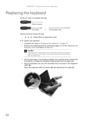
...the steps in "Preparing the notebook" on page 58. Open the keyboard cable connector (b) and disconnect the cable (c). 62 CHAPTER 3: Replacing notebook components Replacing the keyboard Tools you need to complete this task: Phillips #0 screwdriver Flat screwdriver or Non-marring plastic scribe Screws removed during this cable... on page 47. 2 Remove the keyboard cover by performing steps 2-6 of the keyboard slightly, then carefully slide it toward the LCD panel to release the keyboard retaining tabs from the palm rest. 4 Flip the keyboard over onto the touchpad area to access to...
...the steps in "Preparing the notebook" on page 58. Open the keyboard cable connector (b) and disconnect the cable (c). 62 CHAPTER 3: Replacing notebook components Replacing the keyboard Tools you need to complete this task: Phillips #0 screwdriver Flat screwdriver or Non-marring plastic scribe Screws removed during this cable... on page 47. 2 Remove the keyboard cover by performing steps 2-6 of the keyboard slightly, then carefully slide it toward the LCD panel to release the keyboard retaining tabs from the palm rest. 4 Flip the keyboard over onto the touchpad area to access to...
Service Guide
Page 70
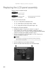
...• 3 black M2.5×6 (keyboard cover) • 2 black M2.5×6 (LCD panel hinges - If there's no wireless card installed, proceed to the notebook through a keyboard cable. top) To replace the LCD panel assembly: 1 Complete the steps in "Preparing the notebook" on page 47. 2 ... notebook has a wireless card installed, complete the steps in "Removing the bay cover" on page 62. CHAPTER 3: Replacing notebook components Replacing the LCD panel assembly Tools you need to complete this task: Phillips #0 screwdriver Flat screwdriver or Non-marring plastic scribe Screws removed...
...• 3 black M2.5×6 (keyboard cover) • 2 black M2.5×6 (LCD panel hinges - If there's no wireless card installed, proceed to the notebook through a keyboard cable. top) To replace the LCD panel assembly: 1 Complete the steps in "Preparing the notebook" on page 47. 2 ... notebook has a wireless card installed, complete the steps in "Removing the bay cover" on page 62. CHAPTER 3: Replacing notebook components Replacing the LCD panel assembly Tools you need to complete this task: Phillips #0 screwdriver Flat screwdriver or Non-marring plastic scribe Screws removed...
Service Guide
Page 72
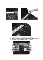
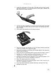
CHAPTER 3: Replacing notebook components 10 Release the antenna cables from their palm rest latches, and then pull them out from underneath the computer. 11 Disconnect the power button board cable from its system board connector, and then release it from its palm rest latches. 12 Carefully open the LCD panel to its fully extended position. 13 Move the LCD, webcam, and microphone cables away from the top hinge screws. 14 Remove the top hinge screws securing the LCD assembly. 66
CHAPTER 3: Replacing notebook components 10 Release the antenna cables from their palm rest latches, and then pull them out from underneath the computer. 11 Disconnect the power button board cable from its system board connector, and then release it from its palm rest latches. 12 Carefully open the LCD panel to its fully extended position. 13 Move the LCD, webcam, and microphone cables away from the top hinge screws. 14 Remove the top hinge screws securing the LCD assembly. 66
Service Guide
Page 73
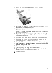
www.gateway.com 15 Lift the LCD panel assembly up . 25 Reinstall the keyboard and the keyboard cover by performing steps 5-8 of the "Replacing the keyboard" procedure on the notebook, and then secure it to its system board connector. 20 Arrange the LCD, webcam, and microphone cables on the palm rest ...and reconnect them to their system board connectors. 21 Close the LCD panel and turn the notebook ...
www.gateway.com 15 Lift the LCD panel assembly up . 25 Reinstall the keyboard and the keyboard cover by performing steps 5-8 of the "Replacing the keyboard" procedure on the notebook, and then secure it to its system board connector. 20 Arrange the LCD, webcam, and microphone cables on the palm rest ...and reconnect them to their system board connectors. 21 Close the LCD panel and turn the notebook ...
Service Guide
Page 74
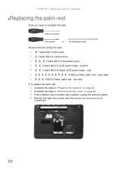
...: • 1 black M2×5 (hard drive) • 1 black M2.5×6 (optical drive) • 3 black M2.5×6 (keyboard cover) • 2 black M2.5×6 (LCD panel hinges - top side) To replace the palm rest: 1 Complete the steps in "Preparing the notebook" on page 47. 2 Complete the steps in "Removing the bay cover" on page...
...: • 1 black M2×5 (hard drive) • 1 black M2.5×6 (optical drive) • 3 black M2.5×6 (keyboard cover) • 2 black M2.5×6 (LCD panel hinges - top side) To replace the palm rest: 1 Complete the steps in "Preparing the notebook" on page 47. 2 Complete the steps in "Removing the bay cover" on page...
Service Guide
Page 75
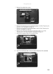
www.gateway.com 5 Remove the optical drive screw. 6 Remove the keyboard cover by performing steps 2-6 of the "Replacing the keyboard cover" procedure on page 58. 7 Remove the keyboard by performing steps 3 and 4 of the "Replacing the keyboard" procedure on page 62. 8 Remove the LCD panel assembly by performing steps 5-15 of the "Replacing the LCD panel assembly" procedure on page 64. 9 Disconnect the speaker cable from the system board. 10 Open the multimedia cable connector (a) and disconnect the cable (b). 69
www.gateway.com 5 Remove the optical drive screw. 6 Remove the keyboard cover by performing steps 2-6 of the "Replacing the keyboard cover" procedure on page 58. 7 Remove the keyboard by performing steps 3 and 4 of the "Replacing the keyboard" procedure on page 62. 8 Remove the LCD panel assembly by performing steps 5-15 of the "Replacing the LCD panel assembly" procedure on page 64. 9 Disconnect the speaker cable from the system board. 10 Open the multimedia cable connector (a) and disconnect the cable (b). 69
Service Guide
Page 77
www.gateway.com 16 Locate the small gaps on the top side of the palm rest and insert ...the palm rest assembly with the screws removed in steps 13 and 15. 22 Reinstall the LCD panel assembly by performing steps 16-23 of the "Replacing the LCD panel assembly" procedure on page 64. 23 Reinstall the keyboard and the keyboard cover by performing... steps 5-8 of the "Replacing the keyboard" procedure on page 62. 24 Return the optical screw drive...
www.gateway.com 16 Locate the small gaps on the top side of the palm rest and insert ...the palm rest assembly with the screws removed in steps 13 and 15. 22 Reinstall the LCD panel assembly by performing steps 16-23 of the "Replacing the LCD panel assembly" procedure on page 64. 23 Reinstall the keyboard and the keyboard cover by performing... steps 5-8 of the "Replacing the keyboard" procedure on page 62. 24 Return the optical screw drive...
Service Guide
Page 78
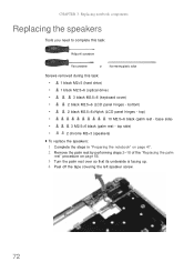
... top) • 10 M2.5×6 black (palm rest - base side) • 3 M2.5×6 black (palm rest - bottom) • 2 black M2.5×6+Nylok (LCD panel hinges - CHAPTER 3: Replacing notebook components Replacing the speakers Tools you need to complete this task: Phillips #0 screwdriver Flat screwdriver or Non-marring plastic scribe Screws removed during this task...
... top) • 10 M2.5×6 black (palm rest - base side) • 3 M2.5×6 black (palm rest - bottom) • 2 black M2.5×6+Nylok (LCD panel hinges - CHAPTER 3: Replacing notebook components Replacing the speakers Tools you need to complete this task: Phillips #0 screwdriver Flat screwdriver or Non-marring plastic scribe Screws removed during this task...
Service Guide
Page 79
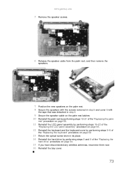
www.gateway.com 5 Remove the speaker screws. 6 Release the speaker cable from the palm rest, and then remove the speakers. 7 Position the new speakers on the palm ... palm rest latches 10 Reinstall the palm rest by performing steps 19-21 of the "Replacing the palm rest" procedure on page 68. 11 Reinstall the LCD panel assembly by performing steps 16-23 of the "Replacing the LCD panel assembly" procedure on page 64. 12 Reinstall the keyboard and the keyboard cover by...
www.gateway.com 5 Remove the speaker screws. 6 Release the speaker cable from the palm rest, and then remove the speakers. 7 Position the new speakers on the palm ... palm rest latches 10 Reinstall the palm rest by performing steps 19-21 of the "Replacing the palm rest" procedure on page 68. 11 Reinstall the LCD panel assembly by performing steps 16-23 of the "Replacing the LCD panel assembly" procedure on page 64. 12 Reinstall the keyboard and the keyboard cover by...
Service Guide
Page 80
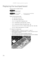
... M2.5×6 black (palm rest - bottom) • 2 black M2.5×6+Nylok (LCD panel hinge - base side) • 3 M2.5×6 black (palm rest - CHAPTER 3: Replacing notebook components Replacing the touchpad board Tools you need to complete this task: Phillips #0 screwdriver Flat screwdriver or...8226; 1 black M2.5×6 (optical drive) • 3 black M2.5×6 (keyboard cover) • 2 black M2.5×6 (LCD panel hinge - top side) To replace the touchpad board: 1 Complete the steps in "Preparing the notebook" on page 47. 2 Remove the palm rest by performing steps 2-18 ...
... M2.5×6 black (palm rest - bottom) • 2 black M2.5×6+Nylok (LCD panel hinge - base side) • 3 M2.5×6 black (palm rest - CHAPTER 3: Replacing notebook components Replacing the touchpad board Tools you need to complete this task: Phillips #0 screwdriver Flat screwdriver or...8226; 1 black M2.5×6 (optical drive) • 3 black M2.5×6 (keyboard cover) • 2 black M2.5×6 (LCD panel hinge - top side) To replace the touchpad board: 1 Complete the steps in "Preparing the notebook" on page 47. 2 Remove the palm rest by performing steps 2-18 ...

Service Guide
Page 82
... in place. 13 Reinstall the palm rest by performing steps 19-21 of the "Replacing the palm rest" procedure on page 68. 14 Reinstall the LCD panel assembly by performing steps 16-23 of the "Replacing the LCD panel assembly" procedure on page 64. 15 Reinstall the keyboard and the keyboard cover ...by performing steps 8 and 9 of the "Replacing the keyboard" procedure on page 54. 18 If you ...
... in place. 13 Reinstall the palm rest by performing steps 19-21 of the "Replacing the palm rest" procedure on page 68. 14 Reinstall the LCD panel assembly by performing steps 16-23 of the "Replacing the LCD panel assembly" procedure on page 64. 15 Reinstall the keyboard and the keyboard cover ...by performing steps 8 and 9 of the "Replacing the keyboard" procedure on page 54. 18 If you ...

Service Guide
Page 83
...gateway.com Replacing the modem board Tools you need to complete this task: Phillips #0 screwdriver Flat screwdriver or Non-marring plastic scribe Screws removed during this task: • 1 black M2×5 (hard drive) • 1 black M2.5×6 (optical drive) • 3 black M2.5×6 (keyboard cover) • 2 black M2.5×6 (LCD... panel hinge - top) • 10 M2.5×6 black (palm rest - top side) • 1 black M2×4 (modem board) To replace the system board: 1 Complete the steps in "Preparing the...
...gateway.com Replacing the modem board Tools you need to complete this task: Phillips #0 screwdriver Flat screwdriver or Non-marring plastic scribe Screws removed during this task: • 1 black M2×5 (hard drive) • 1 black M2.5×6 (optical drive) • 3 black M2.5×6 (keyboard cover) • 2 black M2.5×6 (LCD... panel hinge - top) • 10 M2.5×6 black (palm rest - top side) • 1 black M2×4 (modem board) To replace the system board: 1 Complete the steps in "Preparing the...
Service Guide
Page 164
... 22 Sleep 22 system 22 toggle display 22 Windows 22 wireless Ethernet 24 L latch battery 18 LCD replace 100 LCD assembly lid replace 113 LCD front panel replace 95 LCD panel switching display 22 LCD panel assembly replace 64 LCD panel hinge brackets replace 103 LCD/CRT system key 22 lock Kensington cable 16 M media reader See memory card reader memory bay...
... 22 Sleep 22 system 22 toggle display 22 Windows 22 wireless Ethernet 24 L latch battery 18 LCD replace 100 LCD assembly lid replace 113 LCD front panel replace 95 LCD panel switching display 22 LCD panel assembly replace 64 LCD panel hinge brackets replace 103 LCD/CRT system key 22 lock Kensington cable 16 M media reader See memory card reader memory bay...


