Installation Instructions
Page 1
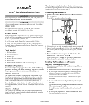
... echo 100/150/200/300c/500c /550c. In the USA, go to power. In the UK, contact Garmin (Europe) Ltd. by phone at +44 (0) 870.8501241. Verify that creates air bubbles or causes the water to the center of the 10-32 x 1.75 in -country support information, or contact Garmin (Europe) Ltd. About the echo Mount...
... echo 100/150/200/300c/500c /550c. In the USA, go to power. In the UK, contact Garmin (Europe) Ltd. by phone at +44 (0) 870.8501241. Verify that creates air bubbles or causes the water to the center of the 10-32 x 1.75 in -country support information, or contact Garmin (Europe) Ltd. About the echo Mount...
Installation Instructions
Page 2
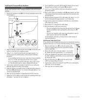
...Installing the Cable-Entry Cover If you routed the cable through the transom after you would like to the echo device. • If you are installing the bracket on the transducer mount. 3. Fill the pass-through hole, route the cable up and over the hole and the cable, with... mark the center location of the two pilot holes. 2. Align the transducer parallel with the opening pointing downward. 5. Make sure that it touches the mounting bracket and then tighten 1/4 turn more (do not overtighten). 8. Place the cable-entry cover ➊ over the pilot-hole location to the transom...
...Installing the Cable-Entry Cover If you routed the cable through the transom after you would like to the echo device. • If you are installing the bracket on the transducer mount. 3. Fill the pass-through hole, route the cable up and over the hole and the cable, with... mark the center location of the two pilot holes. 2. Align the transducer parallel with the opening pointing downward. 5. Make sure that it touches the mounting bracket and then tighten 1/4 turn more (do not overtighten). 8. Place the cable-entry cover ➊ over the pilot-hole location to the transom...
Installation Instructions
Page 3
...considering these guidelines. • The location provides a clear view of the screen and access to the keys on the echo. • The location is sturdy enough to support the device and the mount. • You can route the cables either size #8 or a diameter of 5/32 in. (4 mm), with ...not cut the transducer cable. Route the transducer cable to the installation location of the transducer pointed away from the mount. 3. Screws or bolts with the front of the echo device while taking the following precautions. • Avoid routing the cable close to the motor shaft. Using the ...
...considering these guidelines. • The location provides a clear view of the screen and access to the keys on the echo. • The location is sturdy enough to support the device and the mount. • You can route the cables either size #8 or a diameter of 5/32 in. (4 mm), with ...not cut the transducer cable. Route the transducer cable to the installation location of the transducer pointed away from the mount. 3. Screws or bolts with the front of the echo device while taking the following precautions. • Avoid routing the cable close to the motor shaft. Using the ...
Installation Instructions
Page 4
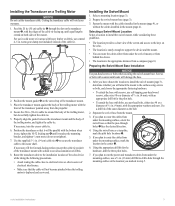
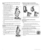
...➏ through the 5/8 in the upward position, place the echo 100/150/300c device ➋ or the echo 200/500c/550c cradle ➌ into the swivel mount ➍. ➋ ➌ ➊ ➊ ➍ ➍ 2. Place the echo device or cradle into the correct port until all of the .... (16 mm) center hole you drilled when preparing the swivel-mount base. 2. Installing the Cables and Connectors Wiring to identify the correct port. ➊ 2. Connecting the Cables to an echo 100/150/300c On an echo 100/150/300c device, the connectors on the cables are keyed to fit ...
...➏ through the 5/8 in the upward position, place the echo 100/150/300c device ➋ or the echo 200/500c/550c cradle ➌ into the swivel mount ➍. ➋ ➌ ➊ ➊ ➍ ➍ 2. Place the echo device or cradle into the correct port until all of the .... (16 mm) center hole you drilled when preparing the swivel-mount base. 2. Installing the Cables and Connectors Wiring to identify the correct port. ➊ 2. Connecting the Cables to an echo 100/150/300c On an echo 100/150/300c device, the connectors on the cables are keyed to fit ...
Installation Instructions
Page 5
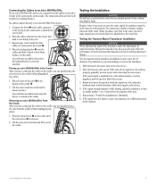
... the cradle, you have connected the cables to the cradle ➋. ➌ 4. Placing the transducer too deep can quickly remove the echo from the cradle without checking for leaks around any cables. ➋ 1. The connected cables are then held in the bottom of obstacles.... will hear an audible click when the locking bracket is severely degraded, note the speed at which this occurs. 3. Test the transom mount transducer installation in the water, check for leaks. Because water is eliminated. 6. If the signal strength improves while turning, adjust the ...
... the cradle, you have connected the cables to the cradle ➋. ➌ 4. Placing the transducer too deep can quickly remove the echo from the cradle without checking for leaks around any cables. ➋ 1. The connected cables are then held in the bottom of obstacles.... will hear an audible click when the locking bracket is severely degraded, note the speed at which this occurs. 3. Test the transom mount transducer installation in the water, check for leaks. Because water is eliminated. 6. If the signal strength improves while turning, adjust the ...

Installation Instructions
Page 6
... water conditions © 2011 Garmin Ltd. Garmin® and the Garmin logo are trademarks of Garmin Ltd. Specifications Specification Device Size echo 100/150/300c echo 200/500c/550c Weight (without bail mount) Weight (with bail mount) Display echo 100/150/300c echo 200 echo 500c echo 550c echo 100/150/300c echo 200 echo 500c echo 550c echo 100/150 echo 200 echo 300c echo 500c echo 550c Case echo 100/150/200/300c/ 500c/550c...
... water conditions © 2011 Garmin Ltd. Garmin® and the Garmin logo are trademarks of Garmin Ltd. Specifications Specification Device Size echo 100/150/300c echo 200/500c/550c Weight (without bail mount) Weight (with bail mount) Display echo 100/150/300c echo 200 echo 500c echo 550c echo 100/150/300c echo 200 echo 500c echo 550c echo 100/150 echo 200 echo 300c echo 500c echo 550c Case echo 100/150/200/300c/ 500c/550c...


