Installation Instructions
Page 2
...2642.9199 Fax 886/2.2642.9099 All rights reserved. IN NO EVENT SHALL GARMIN BE LIABLE FOR ANY INCIDENTAL, SPECIAL, INDIRECT OR CONSEQUENTIAL DAMAGES, WHETHER RESULTING FROM THE USE, MISUSE, OR INABILITY TO USE THIS PRODUCT OR FROM DEFECTS IN THE PRODUCT. To obtain warranty service, ...document is strictly prohibited. A Printed in this manual may not apply to be responsible for current updates and supplemental information concerning the use . Garmin®, DCG®, CANet TM, UltrascrollTM, and DynacolorTM are not eligible for one copy of this manual or of any revision ...
...2642.9199 Fax 886/2.2642.9099 All rights reserved. IN NO EVENT SHALL GARMIN BE LIABLE FOR ANY INCIDENTAL, SPECIAL, INDIRECT OR CONSEQUENTIAL DAMAGES, WHETHER RESULTING FROM THE USE, MISUSE, OR INABILITY TO USE THIS PRODUCT OR FROM DEFECTS IN THE PRODUCT. To obtain warranty service, ...document is strictly prohibited. A Printed in this manual may not apply to be responsible for current updates and supplemental information concerning the use . Garmin®, DCG®, CANet TM, UltrascrollTM, and DynacolorTM are not eligible for one copy of this manual or of any revision ...
Installation Instructions
Page 3
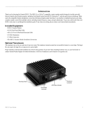
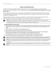
...the coverage area at www.garmin.com. The GSD 21 is a CANetTM compatible, remote sounder module designed to multiple head units, providing complete sounder control from your local dealer or contact Garmin Product Support for choosing the Garmin GSD 21. If any items are... technology. Since mounting locations vary, see your GSD 21, take time to read through this installation guide. Mounting Holes Power/Data Connector LED Status Indicator Transducer Connector GSD 21 Sonar Module 1 When used with compatible Garmin chartplotters, it provides full-featured depth sounder functions...
...the coverage area at www.garmin.com. The GSD 21 is a CANetTM compatible, remote sounder module designed to multiple head units, providing complete sounder control from your local dealer or contact Garmin Product Support for choosing the Garmin GSD 21. If any items are... technology. Since mounting locations vary, see your GSD 21, take time to read through this installation guide. Mounting Holes Power/Data Connector LED Status Indicator Transducer Connector GSD 21 Sonar Module 1 When used with compatible Garmin chartplotters, it provides full-featured depth sounder functions...
Installation Instructions
Page 4
...module should be mounted in an out-of time, be sure there is dry and well ventilated. NOTE: When using the chartplotter and GSD 21 on . Check with the installation, contact Garmin Product Support. If needed, additional mounting holes can be submerged in the side mounting flanges of the ... instructions provided with the transducer. 4. NOTE: You can extend the CANet wiring of the GSD 21 power/data cable up to 100 ft (30 m) total length. Doing so might damage the GSD 21. 2 GSD 21 Sonar Module Be sure to mount the module so that is enough available amperage to secure the...
...module should be mounted in an out-of time, be sure there is dry and well ventilated. NOTE: When using the chartplotter and GSD 21 on . Check with the installation, contact Garmin Product Support. If needed, additional mounting holes can be submerged in the side mounting flanges of the ... instructions provided with the transducer. 4. NOTE: You can extend the CANet wiring of the GSD 21 power/data cable up to 100 ft (30 m) total length. Doing so might damage the GSD 21. 2 GSD 21 Sonar Module Be sure to mount the module so that is enough available amperage to secure the...
Installation Instructions
Page 5
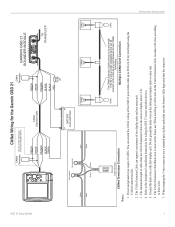
... maximum of the GSD 21 power/data cable up to 80 ft (24.38 m) total length using the CANet Connections Kit. 2. When inserting a CANet unit on the CANet Extension Cable, reconnect all wires according to the chartplotter's installation instructions for wiring the GPS 17 sensor and other devices....wire on the subsequent display units or sonar unit. 6. When crimping the 3-wire connector, use . You can extend the CANet wiring of two display units and one sonar unit. 3. GSD 21 Sonar Module To Sounder Green White CANet Wiring for the Garmin GSD 21 CANet Terminator See the CANet Terminator ...
... maximum of the GSD 21 power/data cable up to 80 ft (24.38 m) total length using the CANet Connections Kit. 2. When inserting a CANet unit on the CANet Extension Cable, reconnect all wires according to the chartplotter's installation instructions for wiring the GPS 17 sensor and other devices....wire on the subsequent display units or sonar unit. 6. When crimping the 3-wire connector, use . You can extend the CANet wiring of two display units and one sonar unit. 3. GSD 21 Sonar Module To Sounder Green White CANet Wiring for the Garmin GSD 21 CANet Terminator See the CANet Terminator ...
Installation Instructions
Page 6
... INSTRUCTIONS 4 Serial Wiring for wiring the GPS 17 sensor and other devices. 4. Refer to the chartplotter's specific Installation Instructions for the Garmin GSD 21 to 100 ft (30 m) total length. Use the CANet Extension Cable or 22 AWG, 4-conductor shielded cable for data connections and 18 AWG for power. 2. GSD 21 Sonar Module Do not ground the drain...
... INSTRUCTIONS 4 Serial Wiring for wiring the GPS 17 sensor and other devices. 4. Refer to the chartplotter's specific Installation Instructions for the Garmin GSD 21 to 100 ft (30 m) total length. Use the CANet Extension Cable or 22 AWG, 4-conductor shielded cable for data connections and 18 AWG for power. 2. GSD 21 Sonar Module Do not ground the drain...
Installation Instructions
Page 7
GSD 21 Sonar Module Serial Wiring for the Garmin GSD 21 to the chartplotter's specific Installation Instructions for power. 2. Use the CANet Extension Cable or 22 AWG, 4-conductor shielded cable for data connections and 18 AWG for wiring the GPS 17 sensor and other devices. 4. When crimping the 3-wire connector, use a standard pair of the GSD 21 power/data cable up to...
GSD 21 Sonar Module Serial Wiring for the Garmin GSD 21 to the chartplotter's specific Installation Instructions for power. 2. Use the CANet Extension Cable or 22 AWG, 4-conductor shielded cable for data connections and 18 AWG for wiring the GPS 17 sensor and other devices. 4. When crimping the 3-wire connector, use a standard pair of the GSD 21 power/data cable up to...
Installation Instructions
Page 8
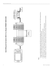
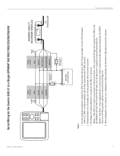
.... When crimping the 3-wire connector, use a standard pair of the GSD 21 power/data cable up to a power source, install a switch between the Orange wire and ground. GSD 21 Sonar Module INSTALLATION INSTRUCTIONS ON OFF 6 Serial Wiring for the Garmin GSD 21 to a circuit that is switched on the sonar unit. 3. Option 1: If the GSD 21 is wired to a Single GPSMAP 276C...
.... When crimping the 3-wire connector, use a standard pair of the GSD 21 power/data cable up to a power source, install a switch between the Orange wire and ground. GSD 21 Sonar Module INSTALLATION INSTRUCTIONS ON OFF 6 Serial Wiring for the Garmin GSD 21 to a circuit that is switched on the sonar unit. 3. Option 1: If the GSD 21 is wired to a Single GPSMAP 276C...
Installation Instructions
Page 9
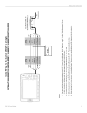
... FUSE 2A BLACK WHITE/BLUE WHITE/BROWN ORANGE BATTERY 10-33 VOLTS DC SEE NOTE 3 OPTION 2 GARMIN GSD 21 SOUNDER MODULE TO TRANSDUCER Notes: 1. When crimping the 3-wire connector, use a standard pair of the GSD 21 power/data cable up to a power source, install a switch between the Orange wire and ground. GSD 21 Sonar Module Serial Wiring for power. 2.
... FUSE 2A BLACK WHITE/BLUE WHITE/BROWN ORANGE BATTERY 10-33 VOLTS DC SEE NOTE 3 OPTION 2 GARMIN GSD 21 SOUNDER MODULE TO TRANSDUCER Notes: 1. When crimping the 3-wire connector, use a standard pair of the GSD 21 power/data cable up to a power source, install a switch between the Orange wire and ground. GSD 21 Sonar Module Serial Wiring for power. 2.
Installation Instructions
Page 10
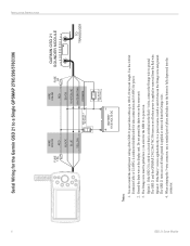
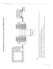
...on the sonar unit. 3. GSD 21 Sonar Module When crimping the 3-wire connector, use a standard pair of the GSD 21 power/data cable up to a Single GPSMAP 172/172C FUSE 2A WIRE COLOR RED BLACK BLUE BROWN ORANGE WIRE COLOR RED FUSE 2A BLACK WHITE/BLUE WHITE/BROWN ORANGE GARMIN GSD 21 SOUNDER ... DC Notes: 1. INSTALLATION INSTRUCTIONS 8 Serial Wiring for the Garmin GSD 21 to 100 ft (30 m) total length. Use the CANet Extension Cable or 22 AWG, 4-conductor shielded cable for data connections and 18 AWG for wiring the GPS 17 sensor and other devices. 4. Ground the drain wire at the ...
...on the sonar unit. 3. GSD 21 Sonar Module When crimping the 3-wire connector, use a standard pair of the GSD 21 power/data cable up to a Single GPSMAP 172/172C FUSE 2A WIRE COLOR RED BLACK BLUE BROWN ORANGE WIRE COLOR RED FUSE 2A BLACK WHITE/BLUE WHITE/BROWN ORANGE GARMIN GSD 21 SOUNDER ... DC Notes: 1. INSTALLATION INSTRUCTIONS 8 Serial Wiring for the Garmin GSD 21 to 100 ft (30 m) total length. Use the CANet Extension Cable or 22 AWG, 4-conductor shielded cable for data connections and 18 AWG for wiring the GPS 17 sensor and other devices. 4. Ground the drain wire at the ...
