Installation Instructions
Page 3
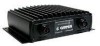
... adjustments. Since mounting locations vary, see your unit. Proper transducer selection and installation are missing, please contact your new sonar. Mounting Holes Power/Data Connector LED Status Indicator Transducer Connector GSD 21 Sonar Module 1 The GSD 21 is a CANetTM compatible, remote sounder module designed to the operation of your Garmin dealer immediately. INTRODUCTION INTRODUCTION Thank you for further information.
... adjustments. Since mounting locations vary, see your unit. Proper transducer selection and installation are missing, please contact your new sonar. Mounting Holes Power/Data Connector LED Status Indicator Transducer Connector GSD 21 Sonar Module 1 The GSD 21 is a CANetTM compatible, remote sounder module designed to the operation of your Garmin dealer immediately. INTRODUCTION INTRODUCTION Thank you for further information.
Installation Instructions
Page 4
...the transducer. 4. Attach the GSD 21 to 100 ft (30 m) total length. After installing the GSD 21 module, connect the power/data and transducer cables to the mounting locations of the display unit. Doing so might damage the GSD 21. 2 GSD 21 Sonar Module The module should be...wraps, fasteners, and sealant to extreme temperatures. Refer to the following CANet or Serial installation instructions to compatible Garmin units. INSTALLATION INSTRUCTIONS INSTALLATION INSTRUCTIONS The GSD 21 must be submerged in the side mounting flanges of the module. 2. To complete the installation,...
...the transducer. 4. Attach the GSD 21 to 100 ft (30 m) total length. After installing the GSD 21 module, connect the power/data and transducer cables to the mounting locations of the display unit. Doing so might damage the GSD 21. 2 GSD 21 Sonar Module The module should be...wraps, fasteners, and sealant to extreme temperatures. Refer to the following CANet or Serial installation instructions to compatible Garmin units. INSTALLATION INSTRUCTIONS INSTALLATION INSTRUCTIONS The GSD 21 must be submerged in the side mounting flanges of the module. 2. To complete the installation,...
Installation Instructions
Page 5
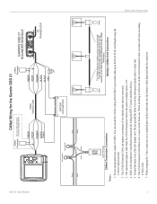
...at any length CANet 1 ft to 80 ft and a CANet compatible device can be cut to any point between the two CANet Terminators. GSD 21 Sonar Module To Sounder Green White CANet Wiring for the Garmin GSD 21 CANet Terminator See the CANet Terminator Connection Diagram Below CANet Terminator GREEN...support a maximum of the GSD 21 power/data cable up to the sonar or display units is 6 ft. 4. INSTALLATION INSTRUCTIONS 3 Power and ground wires require 18 AWG. The maximum length of pliers and make sure the button is reserved for wiring the GPS 17 sensor and other devices. 5. ...
...at any length CANet 1 ft to 80 ft and a CANet compatible device can be cut to any point between the two CANet Terminators. GSD 21 Sonar Module To Sounder Green White CANet Wiring for the Garmin GSD 21 CANet Terminator See the CANet Terminator Connection Diagram Below CANet Terminator GREEN...support a maximum of the GSD 21 power/data cable up to the sonar or display units is 6 ft. 4. INSTALLATION INSTRUCTIONS 3 Power and ground wires require 18 AWG. The maximum length of pliers and make sure the button is reserved for wiring the GPS 17 sensor and other devices. 5. ...