Installation Guide
Page 1
GSD 20 Sounder Module installation instructions
GSD 20 Sounder Module installation instructions
Installation Guide
Page 3
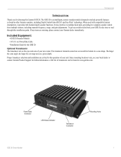
... full-featured depth sounder functions. Included Equipment: • GSD 20 Sounder Module • 30' (9.1 m) Power/Data Cable • Installation Guide for complete sounder control from your GSD 20, take time to the operation of your local dealer or contact Garmin Product Support for choosing the Garmin GSD 20. Power/Data Connector LED Status Indicator Transducer Connector Mounting Holes GSD 20 Sonar Module 1 The transducer...
... full-featured depth sounder functions. Included Equipment: • GSD 20 Sounder Module • 30' (9.1 m) Power/Data Cable • Installation Guide for complete sounder control from your GSD 20, take time to the operation of your local dealer or contact Garmin Product Support for choosing the Garmin GSD 20. Power/Data Connector LED Status Indicator Transducer Connector Mounting Holes GSD 20 Sonar Module 1 The transducer...
Installation Guide
Page 5
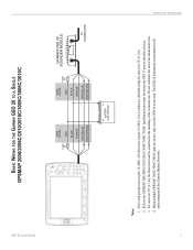
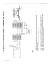
...end of the extension run. All other devices. 3. The GSD 20 information is transmitted to all units connected to one unit. Power and ground wires require 18 AWG. Use 4-conductor, shielded wiring for wiring the GPS 17 sensor and other wires require 22 AWG. For runs over 30...drain wire. 4. GSD 20 Sonar Module BASIC WIRING FOR THE GARMIN GSD 20 TO A SINGLE GPSMAP 2006/2006C/2010/2010C/3005C/3006C/3010C FUSE 5 A WIRE COLOR RED BLACK ORANGE WHITE/BLUE WHITE/BROWN WIRE COLOR RED FUSE 2 A BLACK ORANGE WHITE/BLUE WHITE/BROWN GARMIN GSD 20 SOUNDER MODULE TO TRANSDUCER ...
...end of the extension run. All other devices. 3. The GSD 20 information is transmitted to all units connected to one unit. Power and ground wires require 18 AWG. Use 4-conductor, shielded wiring for wiring the GPS 17 sensor and other wires require 22 AWG. For runs over 30...drain wire. 4. GSD 20 Sonar Module BASIC WIRING FOR THE GARMIN GSD 20 TO A SINGLE GPSMAP 2006/2006C/2010/2010C/3005C/3006C/3010C FUSE 5 A WIRE COLOR RED BLACK ORANGE WHITE/BLUE WHITE/BROWN WIRE COLOR RED FUSE 2 A BLACK ORANGE WHITE/BLUE WHITE/BROWN GARMIN GSD 20 SOUNDER MODULE TO TRANSDUCER ...
Installation Guide
Page 7
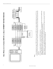
...(9.1 m), the drain wire must be connected to the Red wire. The GSD 20 turns on . Power and ground wires require 18 AWG. GSD 20 Sonar Module BASIC WIRING FOR THE GARMIN GSD 20 TO A SINGLE GPSMAP 276C/296/376C/396 INSTALLATION INSTRUCTIONS ON OFF FUSE ...1.5A WIRE COLOR RED BLACK BLUE YELLOW SEE NOTE 3 ON OPTION 1 OFF WIRE COLOR RED FUSE 2A BLACK WHITE/BLUE WHITE/BROWN ORANGE BATTERY 10-35 VOLTS DC SEE NOTE 3 OPTION 2 GARMIN GSD 20 SOUNDER...
...(9.1 m), the drain wire must be connected to the Red wire. The GSD 20 turns on . Power and ground wires require 18 AWG. GSD 20 Sonar Module BASIC WIRING FOR THE GARMIN GSD 20 TO A SINGLE GPSMAP 276C/296/376C/396 INSTALLATION INSTRUCTIONS ON OFF FUSE ...1.5A WIRE COLOR RED BLACK BLUE YELLOW SEE NOTE 3 ON OPTION 1 OFF WIRE COLOR RED FUSE 2A BLACK WHITE/BLUE WHITE/BROWN ORANGE BATTERY 10-35 VOLTS DC SEE NOTE 3 OPTION 2 GARMIN GSD 20 SOUNDER...
Installation Guide
Page 8
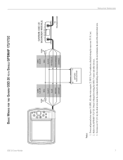
...GSD 20 Sonar Module BASIC WIRING FOR THE GARMIN GSD 20 TO A SINGLE GPSMAP 182/182C/192C/232 FUSE 1.5A WIRE COLOR RED BLACK BLUE BROWN SEE NOTE 3 ON OPTION 1 OFF WIRE COLOR RED FUSE 2A BLACK WHITE/BLUE WHITE/BROWN ORANGE BATTERY 10-35 VOLTS DC SEE NOTE 3 OPTION 2 GARMIN GSD 20 SOUNDER... MODULE TO TRANSDUCER Notes: 1. Power and ground wires require 18 AWG. Use 4-conductor, shielded wiring for the GSD 20 to the shielding of the shield drain wire. 3. The GSD 20 turns on . Option 1: If the GSD 20 is wired to a circuit that is...
...GSD 20 Sonar Module BASIC WIRING FOR THE GARMIN GSD 20 TO A SINGLE GPSMAP 182/182C/192C/232 FUSE 1.5A WIRE COLOR RED BLACK BLUE BROWN SEE NOTE 3 ON OPTION 1 OFF WIRE COLOR RED FUSE 2A BLACK WHITE/BLUE WHITE/BROWN ORANGE BATTERY 10-35 VOLTS DC SEE NOTE 3 OPTION 2 GARMIN GSD 20 SOUNDER... MODULE TO TRANSDUCER Notes: 1. Power and ground wires require 18 AWG. Use 4-conductor, shielded wiring for the GSD 20 to the shielding of the shield drain wire. 3. The GSD 20 turns on . Option 1: If the GSD 20 is wired to a circuit that is...
Installation Guide
Page 9
... run. GSD 20 Sonar Module BASIC WIRING FOR THE GARMIN GSD 20 TO A SINGLE GPSMAP 172/172C FUSE 5A WIRE COLOR RED BLACK BLUE BROWN ORANGE WIRE COLOR RED FUSE 2A BLACK WHITE/BLUE WHITE/BROWN ORANGE GARMIN GSD 20 SOUNDER MODULE TO TRANSDUCER BATTERY 10-35 VOLTS DC Notes: 1. Use 4-conductor, shielded wiring for wiring the GPS 17 sensor and other...
... run. GSD 20 Sonar Module BASIC WIRING FOR THE GARMIN GSD 20 TO A SINGLE GPSMAP 172/172C FUSE 5A WIRE COLOR RED BLACK BLUE BROWN ORANGE WIRE COLOR RED FUSE 2A BLACK WHITE/BLUE WHITE/BROWN ORANGE GARMIN GSD 20 SOUNDER MODULE TO TRANSDUCER BATTERY 10-35 VOLTS DC Notes: 1. Use 4-conductor, shielded wiring for wiring the GPS 17 sensor and other...
Installation Guide
Page 11
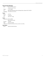
Data Output Source: Proprietary Garmin data format. INSTALLATION INSTRUCTIONS GSD 20 Sonar Module 9 Physical Specifications Size: 6.75" L x 4.75" W x 2.00" H (17.2cm x 12.1cm x 5.1cm) Weight: 1.5 lbs. (.680Kg) Case: Fully gasketed, high-impact plastic and aluminum ...) Frequency: 50/200 kHz Depth: 1500 foot max depth* * Depth capacity is dependent on water salinity, bottom type, and other water conditions. AGC/3AG - 2.0 Amp Sonar Sounder Power: 500 watts (RMS) 4000 watts (peak to 70°C) Power Source: Usage: Fuse: 10-35 Vdc 18 watts max.
Data Output Source: Proprietary Garmin data format. INSTALLATION INSTRUCTIONS GSD 20 Sonar Module 9 Physical Specifications Size: 6.75" L x 4.75" W x 2.00" H (17.2cm x 12.1cm x 5.1cm) Weight: 1.5 lbs. (.680Kg) Case: Fully gasketed, high-impact plastic and aluminum ...) Frequency: 50/200 kHz Depth: 1500 foot max depth* * Depth capacity is dependent on water salinity, bottom type, and other water conditions. AGC/3AG - 2.0 Amp Sonar Sounder Power: 500 watts (RMS) 4000 watts (peak to 70°C) Power Source: Usage: Fuse: 10-35 Vdc 18 watts max.

