Installation Guide
Page 3
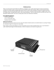
...GSD 20 is an intelligent, remote sounder module designed to include powerful features as the eyes and ears of your new sonar. If any items are critical to read through this installation guide. It may interface to multiple head units, providing for the GSD 20 Optional Transducers The transducer acts as found at a given depth. Included Equipment: • GSD 20...Transducer Connector Mounting Holes GSD 20 Sonar Module 1 Proper transducer selection and installation are missing, please contact your local dealer or contact Garmin Product Support for choosing the Garmin GSD 20...
...GSD 20 is an intelligent, remote sounder module designed to include powerful features as the eyes and ears of your new sonar. If any items are critical to read through this installation guide. It may interface to multiple head units, providing for the GSD 20 Optional Transducers The transducer acts as found at a given depth. Included Equipment: • GSD 20...Transducer Connector Mounting Holes GSD 20 Sonar Module 1 Proper transducer selection and installation are missing, please contact your local dealer or contact Garmin Product Support for choosing the Garmin GSD 20...
Installation Guide
Page 4
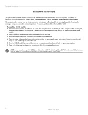
... NOTE: You can be properly installed according to the following wiring diagrams for connecting the GSD 20 to compatible Garmin units. To complete the installation, you experience difficulty with the transducer. 4. Avoid mounting the module where it can extend the wiring of the four mounting ...route and through your Garmin dealer. 2 GSD 20 Sonar Module Be sure to mount the module so that is chosen, place the unit. To install the GSD 20 module: 1. Use 22 AWG, 4-conductor shielded cable for data cable and 18 AWG for attaching the cables. Transducer cable extensions are ...
... NOTE: You can be properly installed according to the following wiring diagrams for connecting the GSD 20 to compatible Garmin units. To complete the installation, you experience difficulty with the transducer. 4. Avoid mounting the module where it can extend the wiring of the four mounting ...route and through your Garmin dealer. 2 GSD 20 Sonar Module Be sure to mount the module so that is chosen, place the unit. To install the GSD 20 module: 1. Use 22 AWG, 4-conductor shielded cable for data cable and 18 AWG for attaching the cables. Transducer cable extensions are ...
Installation Guide
Page 5
... the GSD 20 to the Garmin Marnine Network. GSD 20 Sonar Module BASIC WIRING FOR THE GARMIN GSD 20 TO A SINGLE GPSMAP 2006/2006C/2010/2010C/3005C/3006C/3010C FUSE 5 A WIRE COLOR RED BLACK ORANGE WHITE/BLUE WHITE/BROWN WIRE COLOR RED FUSE 2 A BLACK ORANGE WHITE/BLUE WHITE/BROWN GARMIN GSD 20 SOUNDER MODULE TO TRANSDUCER BATTERY ... the drain wire must be connected to the GPSMAP 2006/2006C/2010/2010C/3005C/3006C/3010C Installation Instructions for wiring the GPS 17 sensor and other wires require 22 AWG. The GSD 20 information is transmitted to all units connected to one unit.
... the GSD 20 to the Garmin Marnine Network. GSD 20 Sonar Module BASIC WIRING FOR THE GARMIN GSD 20 TO A SINGLE GPSMAP 2006/2006C/2010/2010C/3005C/3006C/3010C FUSE 5 A WIRE COLOR RED BLACK ORANGE WHITE/BLUE WHITE/BROWN WIRE COLOR RED FUSE 2 A BLACK ORANGE WHITE/BLUE WHITE/BROWN GARMIN GSD 20 SOUNDER MODULE TO TRANSDUCER BATTERY ... the drain wire must be connected to the GPSMAP 2006/2006C/2010/2010C/3005C/3006C/3010C Installation Instructions for wiring the GPS 17 sensor and other wires require 22 AWG. The GSD 20 information is transmitted to all units connected to one unit.
Installation Guide
Page 7
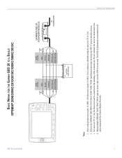
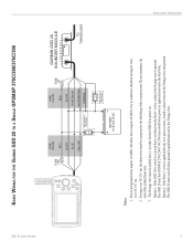
...wire is switched on . All other wires require 22 AWG. Do not terminate the end of the extension run. GSD 20 Sonar Module BASIC WIRING FOR THE GARMIN GSD 20 TO A SINGLE GPSMAP 276C/296/376C/396 INSTALLATION INSTRUCTIONS ON OFF FUSE 1.5A WIRE COLOR RED BLACK BLUE YELLOW SEE... NOTE 3 ON OPTION 1 OFF WIRE COLOR RED FUSE 2A BLACK WHITE/BLUE WHITE/BROWN ORANGE BATTERY 10-35 VOLTS DC SEE NOTE 3 OPTION 2 GARMIN GSD 20 SOUNDER MODULE TO TRANSDUCER...
...wire is switched on . All other wires require 22 AWG. Do not terminate the end of the extension run. GSD 20 Sonar Module BASIC WIRING FOR THE GARMIN GSD 20 TO A SINGLE GPSMAP 276C/296/376C/396 INSTALLATION INSTRUCTIONS ON OFF FUSE 1.5A WIRE COLOR RED BLACK BLUE YELLOW SEE... NOTE 3 ON OPTION 1 OFF WIRE COLOR RED FUSE 2A BLACK WHITE/BLUE WHITE/BROWN ORANGE BATTERY 10-35 VOLTS DC SEE NOTE 3 OPTION 2 GARMIN GSD 20 SOUNDER MODULE TO TRANSDUCER...
Installation Guide
Page 8
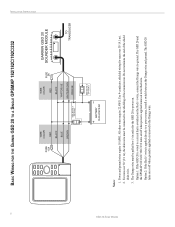
... wired to a circuit that is applied/removed to power on. Use 4-conductor, shielded wiring for the GSD 20 to the Red wire. The GSD 20 and the GPSMAP 182/182C/192C/232 turns on/off when power is switched on or off when ground is applied directly to the... OFF 6 GSD 20 Sonar Module BASIC WIRING FOR THE GARMIN GSD 20 TO A SINGLE GPSMAP 182/182C/192C/232 FUSE 1.5A WIRE COLOR RED BLACK BLUE BROWN SEE NOTE 3 ON OPTION 1 OFF WIRE COLOR RED FUSE 2A BLACK WHITE/BLUE WHITE/BROWN ORANGE BATTERY 10-35 VOLTS DC SEE NOTE 3 OPTION 2 GARMIN GSD 20 SOUNDER MODULE TO TRANSDUCER Notes: 1....
... wired to a circuit that is applied/removed to power on. Use 4-conductor, shielded wiring for the GSD 20 to the Red wire. The GSD 20 and the GPSMAP 182/182C/192C/232 turns on/off when power is switched on or off when ground is applied directly to the... OFF 6 GSD 20 Sonar Module BASIC WIRING FOR THE GARMIN GSD 20 TO A SINGLE GPSMAP 182/182C/192C/232 FUSE 1.5A WIRE COLOR RED BLACK BLUE BROWN SEE NOTE 3 ON OPTION 1 OFF WIRE COLOR RED FUSE 2A BLACK WHITE/BLUE WHITE/BROWN ORANGE BATTERY 10-35 VOLTS DC SEE NOTE 3 OPTION 2 GARMIN GSD 20 SOUNDER MODULE TO TRANSDUCER Notes: 1....
Installation Guide
Page 9
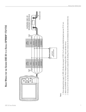
... sensor and other wires require 22 AWG. Refer to the shielding of the shield drain wire. INSTALLATION INSTRUCTIONS 7 GSD 20 Sonar Module BASIC WIRING FOR THE GARMIN GSD 20 TO A SINGLE GPSMAP 172/172C FUSE 5A WIRE COLOR RED BLACK BLUE BROWN ORANGE WIRE COLOR RED FUSE 2A BLACK WHITE/BLUE WHITE/BROWN ORANGE GARMIN GSD 20 SOUNDER MODULE TO TRANSDUCER...
... sensor and other wires require 22 AWG. Refer to the shielding of the shield drain wire. INSTALLATION INSTRUCTIONS 7 GSD 20 Sonar Module BASIC WIRING FOR THE GARMIN GSD 20 TO A SINGLE GPSMAP 172/172C FUSE 5A WIRE COLOR RED BLACK BLUE BROWN ORANGE WIRE COLOR RED FUSE 2A BLACK WHITE/BLUE WHITE/BROWN ORANGE GARMIN GSD 20 SOUNDER MODULE TO TRANSDUCER...


