
Installation Instructions
Page 1
... below eye level to operate the autopilot on the device. • The mounting surface must be installed by the warranty. GHP™ Compact Reactor™ Hydraulic Installation Instructions Important Safety Information WARNING See the Important Safety and Product Information guide in the product specifications. Specific knowledge of multiple components. You should be flat to help understand the mounting and connection considerations. Tools Needed...
... below eye level to operate the autopilot on the device. • The mounting surface must be installed by the warranty. GHP™ Compact Reactor™ Hydraulic Installation Instructions Important Safety Information WARNING See the Important Safety and Product Information guide in the product specifications. Specific knowledge of multiple components. You should be flat to help understand the mounting and connection considerations. Tools Needed...

Installation Instructions
Page 2
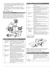
... ECU power cable connects to make sure no magnetic fields are located within 0.5 m (19 in.) of rotation, you should install a manual switch to disable the autopilot if needed , the wires can be installed near the primary helm, so it where you use mounting hardware ... the helm control using a NMEA data cable (NMEA 0183 Connection Considerations, page 9). It detects when you install in the hydraulic steering lines of the GHP Compact Reactor Hydraulic autopilot system. • To avoid interference with a magnetic compass, the device should not be mounted. Helm Control Connection...
... ECU power cable connects to make sure no magnetic fields are located within 0.5 m (19 in.) of rotation, you should install a manual switch to disable the autopilot if needed , the wires can be installed near the primary helm, so it where you use mounting hardware ... the helm control using a NMEA data cable (NMEA 0183 Connection Considerations, page 9). It detects when you install in the hydraulic steering lines of the GHP Compact Reactor Hydraulic autopilot system. • To avoid interference with a magnetic compass, the device should not be mounted. Helm Control Connection...
Installation Instructions
Page 3
... in the hydraulic steering line, and connected to 16 Vdc power source. This cable should be connected to 24 Vdc power source. To extend this cable, use the advanced features of the ECU. In addition, connecting the power cable without a dedicated helm control, the autopilot CCU must be necessary (CCU Mounting and Connection Considerations, page 2). If you install the autopilot without a dedicated...
... in the hydraulic steering line, and connected to 16 Vdc power source. This cable should be connected to 24 Vdc power source. To extend this cable, use the advanced features of the ECU. In addition, connecting the power cable without a dedicated helm control, the autopilot CCU must be necessary (CCU Mounting and Connection Considerations, page 2). If you install the autopilot without a dedicated...

Installation Instructions
Page 4
... can build one using the supplied cables and connectors (Building a Basic NMEA 2000 Network for the Autopilot System, page 8). The CCU must be mounted in a non-submerged location near the center of the existing hydraulic layout before deciding where to mount the pump. If needed, specific connection diagrams are unsure how to install the pump, contact Garmin Product Support. Item Description...
... can build one using the supplied cables and connectors (Building a Basic NMEA 2000 Network for the Autopilot System, page 8). The CCU must be mounted in a non-submerged location near the center of the existing hydraulic layout before deciding where to mount the pump. If needed, specific connection diagrams are unsure how to install the pump, contact Garmin Product Support. Item Description...
Installation Instructions
Page 5
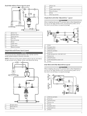
... a Uflex MasterDrive, do not cut the high-pressure line connecting the power unit to the helm to avoid injury or property damage. NOTE: Removal of the power assist-module may be installed between the cylinder and the power-assist module to function correctly. DO NOT CUT Å Return line ...Æ Shutoff valves Ç Uflex MasterDrive power unit È Pump É Dual-Helm with Uflex ...
... a Uflex MasterDrive, do not cut the high-pressure line connecting the power unit to the helm to avoid injury or property damage. NOTE: Removal of the power assist-module may be installed between the cylinder and the power-assist module to function correctly. DO NOT CUT Å Return line ...Æ Shutoff valves Ç Uflex MasterDrive power unit È Pump É Dual-Helm with Uflex ...
Installation Instructions
Page 6
...9 Drill the four 2.8 mm (7/64 in the hardware. You can mount the helm control, you have planned the autopilot installation on the mounting surface. 3 Using a 3 mm (1/8 in the product specifications. Test any mounting hardware with a rotary cutting tool instead of the hole. 6 Place ...necessary, use a 10 mm (3/8 in the intended mounting location and mark the locations of the mounting and wiring considerations for the mounting surface and selected mounting hardware, drill the four holes through a 40 A fuse. Connecting the ECU to Power WARNING When connecting the power cable, do...
...9 Drill the four 2.8 mm (7/64 in the hardware. You can mount the helm control, you have planned the autopilot installation on the mounting surface. 3 Using a 3 mm (1/8 in the product specifications. Test any mounting hardware with a rotary cutting tool instead of the hole. 6 Place ...necessary, use a 10 mm (3/8 in the intended mounting location and mark the locations of the mounting and wiring considerations for the mounting surface and selected mounting hardware, drill the four holes through a 40 A fuse. Connecting the ECU to Power WARNING When connecting the power cable, do...

Installation Instructions
Page 7
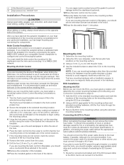
...Installation Mounting the Pump Before you use a clear plastic hose for bleeding a hydraulic steering system. A return line should verify that connects directly to the ECU. 2 Route the bare-wire end of the ECU power cable to the appropriate pump fittings, as a template. 2 Using a drill bit appropriate for more-specific information about bleeding the system. Power Cable Extensions If necessary, the power cable... fluid, fill it can stop turning when you no extension Item Description Splice 10 AWG (5.26 mm²) extension wire Fuse 8 in. (20.3 cm) Battery 8 in. (20.3 cm)...
...Installation Mounting the Pump Before you use a clear plastic hose for bleeding a hydraulic steering system. A return line should verify that connects directly to the ECU. 2 Route the bare-wire end of the ECU power cable to the appropriate pump fittings, as a template. 2 Using a drill bit appropriate for more-specific information about bleeding the system. Power Cable Extensions If necessary, the power cable... fluid, fill it can stop turning when you no extension Item Description Splice 10 AWG (5.26 mm²) extension wire Fuse 8 in. (20.3 cm) Battery 8 in. (20.3 cm)...
Installation Instructions
Page 8
... to the battery directly. 6 Turn on this table. If the cable is shown on your autopilot package does not include a Shadow Drive valve, you plan to 3 seconds after all the parts needed to build one power source should install a manual Single Pole Single Throw (SPST) switch (not included) to disable the autopilot if necessary. 8 1 Route the bare-wire end of...
... to the battery directly. 6 Turn on this table. If the cable is shown on your autopilot package does not include a Shadow Drive valve, you plan to 3 seconds after all the parts needed to build one power source should install a manual Single Pole Single Throw (SPST) switch (not included) to disable the autopilot if necessary. 8 1 Route the bare-wire end of...

Installation Instructions
Page 9
...diagrams. If you install the autopilot without a helm control, all connections and seal them with heat-shrink tubing. • See Specifications, page 11 for a list of Ç the combined T-connectors. These wiring diagrams are output by -side. À 2 Connect the included NMEA 2000 power cable to a 9 to Á 12 Vdc power...optional) or a compatible Garmin chartplotter. See the installation instructions provided with the autopilot system must be connected to a compatible Garmin chartplotter on the NMEA 2000 power cable. 3 Connect the NMEA 2000 power cable to one of the ...
...diagrams. If you install the autopilot without a helm control, all connections and seal them with heat-shrink tubing. • See Specifications, page 11 for a list of Ç the combined T-connectors. These wiring diagrams are output by -side. À 2 Connect the included NMEA 2000 power cable to a 9 to Á 12 Vdc power...optional) or a compatible Garmin chartplotter. See the installation instructions provided with the autopilot system must be connected to a compatible Garmin chartplotter on the NMEA 2000 power cable. 3 Connect the NMEA 2000 power cable to one of the ...

Installation Instructions
Page 10
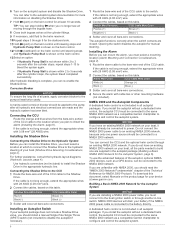
...2000 network (provides power to Ë NMEA 0183 ground) Blue - See the NMEA 0183 section of the NMEA 0183 device is connected to the internal output port 1 on the data cable, you can connect the output port of the internal input ports (port 1, port 2, port 3, or port 4) on the wiring harness. • ...input of the chartplotter owner's manual for the NMEA 2000 bus and the NMEA 0183 device to connect to a common ground. 10 You can connect one receiving (Rx) line, the NMEA 2000 bus and the NMEA 0183 device must be connected to receive data output by your Garmin device, and you ...
...2000 network (provides power to Ë NMEA 0183 ground) Blue - See the NMEA 0183 section of the NMEA 0183 device is connected to the internal output port 1 on the data cable, you can connect the output port of the internal input ports (port 1, port 2, port 3, or port 4) on the wiring harness. • ...input of the chartplotter owner's manual for the NMEA 2000 bus and the NMEA 0183 device to connect to a common ground. 10 You can connect one receiving (Rx) line, the NMEA 2000 bus and the NMEA 0183 device must be connected to receive data output by your Garmin device, and you ...
Installation Instructions
Page 11
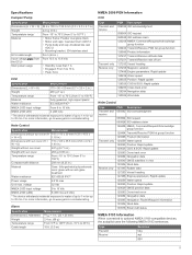
... speed 129025 Position: Rapid update 129029 GNSS position data 129283 Cross-track error 129284 Navigation data 129285 Navigation: Route/Waypoint information 130306 Wind data 130576 Small craft status NMEA 0183 Information When connected to optional NMEA 0183-compatible devices, the autopilot uses the following NMEA 0183 sentences. Helm Control Specification Measurement Dimensions without sun cover...
... speed 129025 Position: Rapid update 129029 GNSS position data 129283 Cross-track error 129284 Navigation data 129285 Navigation: Route/Waypoint information 130306 Wind data 130576 Small craft status NMEA 0183 Information When connected to optional NMEA 0183-compatible devices, the autopilot uses the following NMEA 0183 sentences. Helm Control Specification Measurement Dimensions without sun cover...

Installation Instructions
Page 12
...Autopilot transitions to standby. GHP™, GHC™, Reactor™, and Shadow Drive™ are trademarks of Garmin Ltd. NMEA®, NMEA 2000®, and the NMEA 2000 logo are trademarks of the National Marine Electronics Association. Contacting Garmin Product Support • Go to www.garmin.com/support...in a safe place. Route To maneuver. Garmin® and the Garmin logo are trademarks of Garmin Ltd. autopilot transitions to heading hold Error: Lost Communication Between ECU and CCU (when the autopilot is engaged) Communication between • The ...
...Autopilot transitions to standby. GHP™, GHC™, Reactor™, and Shadow Drive™ are trademarks of Garmin Ltd. NMEA®, NMEA 2000®, and the NMEA 2000 logo are trademarks of the National Marine Electronics Association. Contacting Garmin Product Support • Go to www.garmin.com/support...in a safe place. Route To maneuver. Garmin® and the Garmin logo are trademarks of Garmin Ltd. autopilot transitions to heading hold Error: Lost Communication Between ECU and CCU (when the autopilot is engaged) Communication between • The ...
Configuration Guide
Page 1
... other objects. GHP™ Compact Reactor™ Hydraulic Configuration Guide The autopilot system must be completed in calm water. Dockside Wizard NOTICE If you must configure the autopilot system using a GPS device as a speed source. • If you connected one or more NMEA 2000 compatible engines to your boat. When you have a boat with a power assist steering system, turn the boat...
... other objects. GHP™ Compact Reactor™ Hydraulic Configuration Guide The autopilot system must be completed in calm water. Dockside Wizard NOTICE If you must configure the autopilot system using a GPS device as a speed source. • If you connected one or more NMEA 2000 compatible engines to your boat. When you have a boat with a power assist steering system, turn the boat...

Configuration Guide
Page 2
...is connected to GPS, configure the planing speed. • On a power boat with the Course over -steering after making a turn. Performing the ...screen, select Menu > Setup > Dealer Autopilot Setup > Autopilot Tuning > Autotune > Begin. • If you can review the gain values provided on a chartplotter, select Settings > My Vessel > Autopilot Installation Setup > Autopilot Tuning > Autotune > Begin. During this procedure outside of open water available. When the Autotune procedure is shown. Setting the Fine Heading Adjustment This procedure appears only if you must have a GPS...
...is connected to GPS, configure the planing speed. • On a power boat with the Course over -steering after making a turn. Performing the ...screen, select Menu > Setup > Dealer Autopilot Setup > Autopilot Tuning > Autotune > Begin. • If you can review the gain values provided on a chartplotter, select Settings > My Vessel > Autopilot Installation Setup > Autopilot Tuning > Autotune > Begin. During this procedure outside of open water available. When the Autotune procedure is shown. Setting the Fine Heading Adjustment This procedure appears only if you must have a GPS...

Configuration Guide
Page 3
... > Autopilot Installation Setup > Compass Setup > Fine Heading Adjustment > Begin. 2 Adjust the fine heading setting until the autopilot performance is satisfactory. To use the configuration options is not recommended, and you should turn overshoot. An overactive autopilot can run the autotune process, calibrate the compass, and define north on the autopilot without running the wizards. Advanced Configuration Settings You can drain the battery...
... > Autopilot Installation Setup > Compass Setup > Fine Heading Adjustment > Begin. 2 Adjust the fine heading setting until the autopilot performance is satisfactory. To use the configuration options is not recommended, and you should turn overshoot. An overactive autopilot can run the autotune process, calibrate the compass, and define north on the autopilot without running the wizards. Advanced Configuration Settings You can drain the battery...

Configuration Guide
Page 4
... to compare the RPM readings on -screen instructions. NMEA 2000 or Proprietary, Tachometer, or GPS. This setting applies when the vessel operates below planing speed. If the option for Dealer Autopilot Setup is typically completed automatically through wizards, you can manually adjust any settingsDetailed Configuration Settings, page 4. 1 On a helm control, enable Dealer Mode (Enabling Dealer Configuration on the Helm...
... to compare the RPM readings on -screen instructions. NMEA 2000 or Proprietary, Tachometer, or GPS. This setting applies when the vessel operates below planing speed. If the option for Dealer Autopilot Setup is typically completed automatically through wizards, you can manually adjust any settingsDetailed Configuration Settings, page 4. 1 On a helm control, enable Dealer Mode (Enabling Dealer Configuration on the Helm...

Configuration Guide
Page 5
or its subsidiaries. GHP™, GHC™, Reactor™, and Shadow Drive™ are trademarks of Garmin Ltd. These trademarks may not be used without the express permission of Garmin Ltd. Garmin® and the Garmin logo are trademarks of Garmin. Configuring the Autopilot 5 You can test and reverse the steering direction if necessary. Allows you to set the direction the rudder must move to turn the vessel to port and to starboard. or its subsidiaries, registered in the USA and other countries.
or its subsidiaries. GHP™, GHC™, Reactor™, and Shadow Drive™ are trademarks of Garmin Ltd. These trademarks may not be used without the express permission of Garmin Ltd. Garmin® and the Garmin logo are trademarks of Garmin. Configuring the Autopilot 5 You can test and reverse the steering direction if necessary. Allows you to set the direction the rudder must move to turn the vessel to port and to starboard. or its subsidiaries, registered in the USA and other countries.


