
Battery Charger User's Guide
Page 1
Battery Charger Components Power Indicator LED The Power Indicator LED is on your battery charger. We strongly recommend that you read this guide before using the battery charger even if you are already familiar with computers. BATTERY CHARGER COMPONENTS Battery Connector 1 Battery Connector 2 Power Indicator LED AC Adapter Connector Charge Indicator LEDs Figure 1. Fujitsu Computer Systems Corporation Battery Charger User's Guide This user's guide contains information on when power is being supplied from the AC adapter. 1
Battery Charger Components Power Indicator LED The Power Indicator LED is on your battery charger. We strongly recommend that you read this guide before using the battery charger even if you are already familiar with computers. BATTERY CHARGER COMPONENTS Battery Connector 1 Battery Connector 2 Power Indicator LED AC Adapter Connector Charge Indicator LEDs Figure 1. Fujitsu Computer Systems Corporation Battery Charger User's Guide This user's guide contains information on when power is being supplied from the AC adapter. 1
Battery Charger User's Guide
Page 2
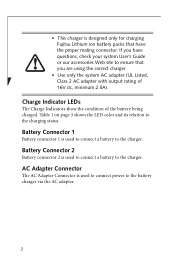
... the charging status. Charge Indicator LEDs The Charge Indicators show the condition of 16V dc, minimum 2.5A). • This charger is designed only for charging Fujitsu Lithium ion battery packs that you have questions, check your system User's Guide or our accessories Web site to ensure that have the proper mating...
... the charging status. Charge Indicator LEDs The Charge Indicators show the condition of 16V dc, minimum 2.5A). • This charger is designed only for charging Fujitsu Lithium ion battery packs that you have questions, check your system User's Guide or our accessories Web site to ensure that have the proper mating...

Battery Charger User's Guide
Page 3
BATTERY CHARGER OPERATION The Power Indicator LED is on when the battery charger is wrong with the battery, the Charging Indicator LED will blink red. If this happens, immediately remove the battery from the charger. 3 Indicator Status • If the charger detects that something is connected to the charger or the condition of the charger itself, as shown in Table 1. If this happens, immediately disconnect the AC adapter and remove the battery from the charger. • If the battery charger detects a failure in AC adapter. Charge Indicator Flashes orange Steady orange ...
BATTERY CHARGER OPERATION The Power Indicator LED is on when the battery charger is wrong with the battery, the Charging Indicator LED will blink red. If this happens, immediately remove the battery from the charger. 3 Indicator Status • If the charger detects that something is connected to the charger or the condition of the charger itself, as shown in Table 1. If this happens, immediately disconnect the AC adapter and remove the battery from the charger. • If the battery charger detects a failure in AC adapter. Charge Indicator Flashes orange Steady orange ...

Battery Charger User's Guide
Page 4
This is a safety feature designed to prevent damage to the battery. Connect the battery charger to align the battery and charger properly. (Figure 3) 4 The Power Indicator LED will light up and the Charging Indicator LED(s) will standby for charging until the battery returns to normal temperature. This is a safety feature to prevent damage to the battery. Plug the AC adapter into an AC outlet. (Figure 2) 3. Be very careful to the AC adapter. 2. When the Charging Indicator LED(s) turns off, align the plastic key pin of the battery connector with the corresponding guide in the battery ...
This is a safety feature designed to prevent damage to the battery. Connect the battery charger to align the battery and charger properly. (Figure 3) 4 The Power Indicator LED will light up and the Charging Indicator LED(s) will standby for charging until the battery returns to normal temperature. This is a safety feature to prevent damage to the battery. Plug the AC adapter into an AC outlet. (Figure 2) 3. Be very careful to the AC adapter. 2. When the Charging Indicator LED(s) turns off, align the plastic key pin of the battery connector with the corresponding guide in the battery ...

Battery Charger User's Guide
Page 5
Figure 2. • The charger can have two batteries connected at the same time, but it charges only one at a time. Connecting the AC Adapter 5 The Charging Indicator LED(s) will turn green when charging is charged first. The battery that was connected first is completed. The second battery is held in a wait status until the first battery is being charged. 6. The Charging Indicator LED(s) will turn orange when the battery(s) is completely charged. • Charging time varies depending on the environmental conditions (such as temperature) or deterioration of the battery(s). 5....
Figure 2. • The charger can have two batteries connected at the same time, but it charges only one at a time. Connecting the AC Adapter 5 The Charging Indicator LED(s) will turn green when charging is charged first. The battery that was connected first is completed. The second battery is held in a wait status until the first battery is being charged. 6. The Charging Indicator LED(s) will turn orange when the battery(s) is completely charged. • Charging time varies depending on the environmental conditions (such as temperature) or deterioration of the battery(s). 5....
Battery Charger User's Guide
Page 6
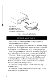
Connecting the battery CARE AND MAINTENANCE • Never connect the battery charger to remove the adapter. has gotten inside. 6 your Fujitsu reseller (see "Fujitsu Computer Systems Contact Information" below). Figure 3. Always remove by grasping the plug body. • If the battery charger smokes, smells strange, heats abnormally, or makes ...
Connecting the battery CARE AND MAINTENANCE • Never connect the battery charger to remove the adapter. has gotten inside. 6 your Fujitsu reseller (see "Fujitsu Computer Systems Contact Information" below). Figure 3. Always remove by grasping the plug body. • If the battery charger smokes, smells strange, heats abnormally, or makes ...
Battery Charger User's Guide
Page 7
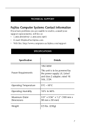
... are unable to resolve, consult your support representative, toll free at: • 1-800-8FUJITSU (1-800-838-5487) • E-mail: 8fujitsu@us.fujitsu.com • Web Site: http://www.computers.us.fujitsu.com/support SPECIFICATIONS Specification Power Requirements Operating Temperature Operating Humidity Maximum Outer Dimensions Weight Details 16V/40W This unit is to...
... are unable to resolve, consult your support representative, toll free at: • 1-800-8FUJITSU (1-800-838-5487) • E-mail: 8fujitsu@us.fujitsu.com • Web Site: http://www.computers.us.fujitsu.com/support SPECIFICATIONS Specification Power Requirements Operating Temperature Operating Humidity Maximum Outer Dimensions Weight Details 16V/40W This unit is to...

Battery Charger User's Guide
Page 8
... Model FJBC-GP (FCS Part Number FPCBC26) Complies with Part 15 of Conformity Model Name: Battery Charger FJBC-GP Conformance to FCC Part 15 Responsible Fujitsu Computer Systems Corporation Party Name: Address: 1250 E. DECLARATION OF CONFORMITY according to Directive(s)/Product Standard: 89/336/EEC and 73/23/EEC 8 Arques Avenue (M/S 122...
... Model FJBC-GP (FCS Part Number FPCBC26) Complies with Part 15 of Conformity Model Name: Battery Charger FJBC-GP Conformance to FCC Part 15 Responsible Fujitsu Computer Systems Corporation Party Name: Address: 1250 E. DECLARATION OF CONFORMITY according to Directive(s)/Product Standard: 89/336/EEC and 73/23/EEC 8 Arques Avenue (M/S 122...

Battery Charger User's Guide
Page 9
If this equipment does cause harmful interference to radio or television reception, which can be determined by turning the equipment off and on a different circuit than the receiver. • Consult the dealer or an experienced radio/TV technician for help. Shielded interconnect cables must be operated at a maximum ambient temperature of 35° C (95° F). 9 DOC (Industry Canada) Notices Notice to provide reasonable protection against harmful interference in accordance with the pertinent RF emission limits governing this equipment to ensure compliance with the instructions, may ...
If this equipment does cause harmful interference to radio or television reception, which can be determined by turning the equipment off and on a different circuit than the receiver. • Consult the dealer or an experienced radio/TV technician for help. Shielded interconnect cables must be operated at a maximum ambient temperature of 35° C (95° F). 9 DOC (Industry Canada) Notices Notice to provide reasonable protection against harmful interference in accordance with the pertinent RF emission limits governing this equipment to ensure compliance with the instructions, may ...

Battery Charger User's Guide
Page 12
...com For technical support call:1-800-8FUJITSU (1-800-838-5487) or e-mail us at: 8fujitsu@us.fujitsu.com Fujitsu and the Fujitsu logo are the property of Fujitsu Ltd. All other reproductive harm. Specifications are subject to the State of factors. B5FY-8881-01EN-00... to cause birth defects or other trademarks mentioned herein are registered trademarks of their respective owners. Fujitsu Computer Systems Corporation 1250 E. Product description data reflects Fujitsu design objectives and is provided for comparative purposes; actual results may vary based on this product ...
...com For technical support call:1-800-8FUJITSU (1-800-838-5487) or e-mail us at: 8fujitsu@us.fujitsu.com Fujitsu and the Fujitsu logo are the property of Fujitsu Ltd. All other reproductive harm. Specifications are subject to the State of factors. B5FY-8881-01EN-00... to cause birth defects or other trademarks mentioned herein are registered trademarks of their respective owners. Fujitsu Computer Systems Corporation 1250 E. Product description data reflects Fujitsu design objectives and is provided for comparative purposes; actual results may vary based on this product ...
T4215 BIOS Guide
Page 2
...; System Data Security feature parameters, such as detailed in the next section): 1. Press [F2] once the Fujitsu logo appears on the screen. Using the TrustedCore Menu When the Fujitsu logo appears on the screen. Pressing the [F1] key gives you to navigate the setup utility menus: 1....Clicking on the left mouse or touchpad button; Pressing the [F10] key saves the current configuration and exits the BIOS Setup Utility. LifeBook T Series Tablet PC T Series BIOS BIOS SETUP UTILITY The BIOS Setup Utility is a program that does not agree with the parameter settings stored in your...
...; System Data Security feature parameters, such as detailed in the next section): 1. Press [F2] once the Fujitsu logo appears on the screen. Using the TrustedCore Menu When the Fujitsu logo appears on the screen. Pressing the [F1] key gives you to navigate the setup utility menus: 1....Clicking on the left mouse or touchpad button; Pressing the [F10] key saves the current configuration and exits the BIOS Setup Utility. LifeBook T Series Tablet PC T Series BIOS BIOS SETUP UTILITY The BIOS Setup Utility is a program that does not agree with the parameter settings stored in your...

T4215 BIOS Guide
Page 3
... require it will give you want to continue with the boot process and start the operating system anyway, press the [F1] key. ■ If your tablet emits a series of the setup utility, as described in the following steps: 1. Press any key to run SETUP 2. When the setup utility starts with a fault...
... require it will give you want to continue with the boot process and start the operating system anyway, press the [F1] key. ■ If your tablet emits a series of the setup utility, as described in the following steps: 1. Press any key to run SETUP 2. When the setup utility starts with a fault...

T4215 BIOS Guide
Page 4
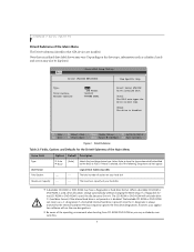
...:SS). PhoenixBIOS Setup Utility Main Advanced Security Boot Info Exit System Time: System Date: Drive0 Drive1 Language: [02:34:56] [06/08/2006] [FUJITSU MHV2040BH] [DV-W24E] [English (US)] Item Specific Help Adjust calendar clock. , , or selects field. ▲ ▲▲ F1 Help ESC... is in a 24 hour for the Main Menu Menu Field Options Default Description System Time: -- -- mat of the time separately. LifeBook T Series Tablet PC MAIN MENU - Move between the seg- SETTING STANDARD SYSTEM PARAMETERS The Main Menu allows you to help understand the field's use. Sets...
...:SS). PhoenixBIOS Setup Utility Main Advanced Security Boot Info Exit System Time: System Date: Drive0 Drive1 Language: [02:34:56] [06/08/2006] [FUJITSU MHV2040BH] [DV-W24E] [English (US)] Item Specific Help Adjust calendar clock. , , or selects field. ▲ ▲▲ F1 Help ESC... is in a 24 hour for the Main Menu Menu Field Options Default Description System Time: -- -- mat of the time separately. LifeBook T Series Tablet PC MAIN MENU - Move between the seg- SETTING STANDARD SYSTEM PARAMETERS The Main Menu allows you to help understand the field's use. Sets...

T4215 BIOS Guide
Page 5
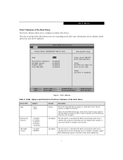
rately. Selects the display language for this interface. Pressing the Enter key selects the Serial ATA Drive1 submenu allowing additional device configuration options for the BIOS. 5 Pressing the Enter key selects the Drive0 submenu allowing additional device configuration options for the Main Menu Menu Field Options Default Description System Date: -- -- Drive1: Selects the Drive1 Serial ATA drive submenu The product number of the hard drive. Date is one. Drive0 Selects the Drive0 Serial ATA drive submenu The product number of the CD-ROM drive. Display the type...
rately. Selects the display language for this interface. Pressing the Enter key selects the Serial ATA Drive1 submenu allowing additional device configuration options for the BIOS. 5 Pressing the Enter key selects the Drive0 submenu allowing additional device configuration options for the Main Menu Menu Field Options Default Description System Date: -- -- Drive1: Selects the Drive1 Serial ATA drive submenu The product number of the hard drive. Date is one. Drive0 Selects the Drive0 Serial ATA drive submenu The product number of the CD-ROM drive. Display the type...
T4215 BIOS Guide
Page 6
... on boot time. [None] The drive is used , drive allocations change automatically without changing the BIOS setup. LifeBook T Series Tablet PC Drive0 Submenu of the following Setup items do not appear. PhoenixBIOS Setup Utility Main Drive0 [FUJITSU MHV2040BH] Item Specific Help Type: Total Sectors: Maximum Capacity: [Auto] LBA Format 78140160 40008MB SATA1 Select Serial...
... on boot time. [None] The drive is used , drive allocations change automatically without changing the BIOS setup. LifeBook T Series Tablet PC Drive0 Submenu of the following Setup items do not appear. PhoenixBIOS Setup Utility Main Drive0 [FUJITSU MHV2040BH] Item Specific Help Type: Total Sectors: Maximum Capacity: [Auto] LBA Format 78140160 40008MB SATA1 Select Serial...
T4215 BIOS Guide
Page 7
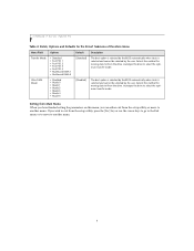
Depending on boot time. [None] The drive is selected, all of the Main Menu The Drive1 submenu allows you to configure secondary ATA devices. Tap the spacebar to have the type automatically identified by the BIOS at POST. F1 Help ESC Exit Select Item Select Menu -/Space Change Values F9 Setup Defaults ▲ Enter Select Sub-Menu F10 Save and Exit Figure 3. Selects the ATA/ATAPI device type. If None is disabled. Main Menu Drive1 Submenu of the following setup items do not appear. Drive1 Submenu Table 3: Fields, Options and Defaults for multiple sector transfer. [...
Depending on boot time. [None] The drive is selected, all of the Main Menu The Drive1 submenu allows you to configure secondary ATA devices. Tap the spacebar to have the type automatically identified by the BIOS at POST. F1 Help ESC Exit Select Item Select Menu -/Space Change Values F9 Setup Defaults ▲ Enter Select Sub-Menu F10 Save and Exit Figure 3. Selects the ATA/ATAPI device type. If None is disabled. Main Menu Drive1 Submenu of the following setup items do not appear. Drive1 Submenu Table 3: Fields, Options and Defaults for multiple sector transfer. [...
T4215 BIOS Guide
Page 8
... setup utility, press the [Esc] key or use the cursor keys to go to the Exit menu or to move to exit from the drive. LifeBook T Series Tablet PC Table 3: Fields, Options and Defaults for the Drive1 Submenu of the Main Menu Menu Field Options Transfer Mode: • Standard • Fast PIO 1 •...
... setup utility, press the [Esc] key or use the cursor keys to go to the Exit menu or to move to exit from the drive. LifeBook T Series Tablet PC Table 3: Fields, Options and Defaults for the Drive1 Submenu of the Main Menu Menu Field Options Transfer Mode: • Standard • Fast PIO 1 •...

T4215 BIOS Guide
Page 9
PhoenixBIOS Setup Utility Main Advanced Security Boot Info Exit IrDA Port Configurations Keyboard/Mouse Features Video Features Internal Device Configurations CPU Features USB Features Miscellaneous Configurations Event Logging Item Specific Help Configures IrDA ports. ▲ ▲ F1 Help ESC Exit Select Item -/Space Change Values F9 Setup Defaults ▲ Select Menu Enter Select Sub-Menu F10 Save and Exit Figure 4. Main Menu ADVANCED MENU - Advanced Menu 9 SETTING DEVICE FEATURE CONTROLS The Advanced Menu allows you to: ■ Set the I/O addresses for the infrared ports...
PhoenixBIOS Setup Utility Main Advanced Security Boot Info Exit IrDA Port Configurations Keyboard/Mouse Features Video Features Internal Device Configurations CPU Features USB Features Miscellaneous Configurations Event Logging Item Specific Help Configures IrDA ports. ▲ ▲ F1 Help ESC Exit Select Item -/Space Change Values F9 Setup Defaults ▲ Select Menu Enter Select Sub-Menu F10 Save and Exit Figure 4. Main Menu ADVANCED MENU - Advanced Menu 9 SETTING DEVICE FEATURE CONTROLS The Advanced Menu allows you to: ■ Set the I/O addresses for the infrared ports...

T4215 BIOS Guide
Page 10
... When selected, opens the CPU Features submenu, which allows setting of the display parameters, including routing of video signals to modify settings for infrared ports. LifeBook T Series Tablet PC Table 4: Fields, Options and Defaults for the Advanced Menu Menu Field Description IrDA Port Configurations When selected, opens the IrDA Port Configurations submenu which...
... When selected, opens the CPU Features submenu, which allows setting of the display parameters, including routing of video signals to modify settings for infrared ports. LifeBook T Series Tablet PC Table 4: Fields, Options and Defaults for the Advanced Menu Menu Field Description IrDA Port Configurations When selected, opens the IrDA Port Configurations submenu which...

T4215 BIOS Guide
Page 11
... disabled. [Enabled] The port is required. IrDA Port Configuration Submenu 11 If you must change the settings, you can be entered in hexadecimal. See your tablet will not function normally. Please keep a record of original settings before making any two ports or devices have the same I/O address assigned your hardware and...
... disabled. [Enabled] The port is required. IrDA Port Configuration Submenu 11 If you must change the settings, you can be entered in hexadecimal. See your tablet will not function normally. Please keep a record of original settings before making any two ports or devices have the same I/O address assigned your hardware and...
