Manual/User Guide
Page 1
C141-E274 3-1 CHAPTER 3 Installation Conditions 3.1 Dimensions 3.2 Mounting 3.3 Connections with Host System This chapter gives the external dimensions, installation conditions, surface temperature conditions, cable connections, and switch settings of the hard disk drives.
C141-E274 3-1 CHAPTER 3 Installation Conditions 3.1 Dimensions 3.2 Mounting 3.3 Connections with Host System This chapter gives the external dimensions, installation conditions, surface temperature conditions, cable connections, and switch settings of the hard disk drives.
Manual/User Guide
Page 2
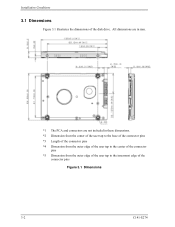
All dimensions are in mm. *1 The PCA and connectors are not included in these dimensions. *2 Dimension from the center of the user tap to the base of the connector pins *3 Length of the connector pins *4 Dimension from the outer edge of the user tap to the center of the connector pins *5 Dimension from the outer edge of the user tap to the innermost edge of the disk drive. Installation Conditions 3.1 Dimensions Figure 3.1 illustrates the dimensions of the connector pins Figure 3.1 Dimensions 3-2 C141-E274
All dimensions are in mm. *1 The PCA and connectors are not included in these dimensions. *2 Dimension from the center of the user tap to the base of the connector pins *3 Length of the connector pins *4 Dimension from the outer edge of the user tap to the center of the connector pins *5 Dimension from the outer edge of the user tap to the innermost edge of the disk drive. Installation Conditions 3.1 Dimensions Figure 3.1 illustrates the dimensions of the connector pins Figure 3.1 Dimensions 3-2 C141-E274
Manual/User Guide
Page 3
... length should satisfy the specification in any direction. (2) Frame The MR head bias of the HDD disk enclosure (DE) is zero. The mounting frame is attached. 3.2 Mounting 3.2 Mounting For information on mounting, see the "FUJITSU 2.5-INCH HDD INTEGRATION GUIDANCE (C141-E144)." (1) Orientation The disk drives can be 0.49N•m (5kgf•cm). C141-E274 3-3
... length should satisfy the specification in any direction. (2) Frame The MR head bias of the HDD disk enclosure (DE) is zero. The mounting frame is attached. 3.2 Mounting 3.2 Mounting For information on mounting, see the "FUJITSU 2.5-INCH HDD INTEGRATION GUIDANCE (C141-E144)." (1) Orientation The disk drives can be 0.49N•m (5kgf•cm). C141-E274 3-3
Manual/User Guide
Page 6
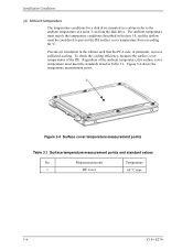
... in the cabinet such that the PCA side, in Table 3.1. Installation Conditions (4) Ambient temperature The temperature conditions for a disk drive mounted in a cabinet refer to prevent the DE surface cover temperature from the disk drive. Regardless of the DE. The ambient temperature must satisfy the temperature conditions described in Section 1.4, and the airflow must...
... in the cabinet such that the PCA side, in Table 3.1. Installation Conditions (4) Ambient temperature The temperature conditions for a disk drive mounted in a cabinet refer to prevent the DE surface cover temperature from the disk drive. Regardless of the DE. The ambient temperature must satisfy the temperature conditions described in Section 1.4, and the airflow must...
Manual/User Guide
Page 7
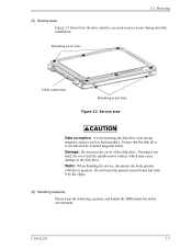
...Damage: Do not press the cover of the disk drive. Static: When handling the device, disconnect the body ground (500 kΩ or greater). Pressing it by external magnetic fields. Do not touch the printed circuit board, but hold it too hard, the cover and the spindle motor contact, which... may cause damage to the disk drive. 3.2 Mounting (5) Service area Figure 3.5 shows how the drive must be accessed (service areas) during and after installation. Ensure that the disk drive is not affected by the edges. ...
...Damage: Do not press the cover of the disk drive. Static: When handling the device, disconnect the body ground (500 kΩ or greater). Pressing it by external magnetic fields. Do not touch the printed circuit board, but hold it too hard, the cover and the spindle motor contact, which... may cause damage to the disk drive. 3.2 Mounting (5) Service area Figure 3.5 shows how the drive must be accessed (service areas) during and after installation. Ensure that the disk drive is not affected by the edges. ...
Manual/User Guide
Page 9
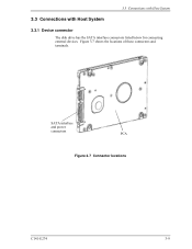
Figure 3.7 shows the locations of these connectors and terminals. 3.3 Connections with Host System 3.3 Connections with Host System 3.3.1 Device connector The disk drive has the SATA interface connectors listed below for connecting external devices. SATA interface and power connectors PCA Figure 3.7 Connector locations C141-E274 3-9
Figure 3.7 shows the locations of these connectors and terminals. 3.3 Connections with Host System 3.3 Connections with Host System 3.3.1 Device connector The disk drive has the SATA interface connectors listed below for connecting external devices. SATA interface and power connectors PCA Figure 3.7 Connector locations C141-E274 3-9
Manual/User Guide
Page 10
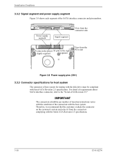
... evaluate the connector on the customer's system and select it from the PCA side Figure 3.8 Power supply pins (CN1) 3.3.3 Connector specifications for mating with the disk drive must be compliant with the host system. For detail of the SATA interface connector and pin numbers.
... evaluate the connector on the customer's system and select it from the PCA side Figure 3.8 Power supply pins (CN1) 3.3.3 Connector specifications for mating with the disk drive must be compliant with the host system. For detail of the SATA interface connector and pin numbers.
Manual/User Guide
Page 11
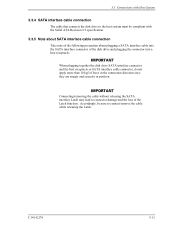
... the cable while releasing the Latch. Accordingly, be compliant with Host System 3.3.4 SATA interface cable connection The cable that connects the disk drive to the host system must be sure to connector damage and the loss of force in the connection direction once they are snugly ... of the following precaution about plugging a SATA interface cable into the SATA interface connector of the disk drive and plugging the connector into a host receptacle: When plugging together the disk drive SATA interface connector and the host receptacle or SATA interface cable connector, do not apply more than...
... the cable while releasing the Latch. Accordingly, be compliant with Host System 3.3.4 SATA interface cable connection The cable that connects the disk drive to the host system must be sure to connector damage and the loss of force in the connection direction once they are snugly ... of the following precaution about plugging a SATA interface cable into the SATA interface connector of the disk drive and plugging the connector into a host receptacle: When plugging together the disk drive SATA interface connector and the host receptacle or SATA interface cable connector, do not apply more than...


