
Product Manual
Page 4
.../996D Rev.8c [NCITS.306:1998] T10/1157D Rev.24 T10/1365D Rev.10 Title SCSI Primary Commands-2 (SPC-2) SCSI-3 Block Commands (SBC) SCSI Architecture Model-2 (SAM-2) SCSI Parallel Interface-4 (SPI-4) *1 ANSI = American National Standard Institute In case of conflict between this manual and any referenced document, this manual comply with...
.../996D Rev.8c [NCITS.306:1998] T10/1157D Rev.24 T10/1365D Rev.10 Title SCSI Primary Commands-2 (SPC-2) SCSI-3 Block Commands (SBC) SCSI Architecture Model-2 (SAM-2) SCSI Parallel Interface-4 (SPI-4) *1 ANSI = American National Standard Institute In case of conflict between this manual and any referenced document, this manual comply with...
Product Manual
Page 7
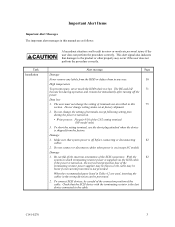
...prevent injury, never touch the HDD while it is hot. The DE and LSI 71 become hot during the power is turned on .(except NC model) Damage 1. To short the setting terminal, use the short plug attached when the device is turned on, the overcurrent protection fuse of the ...CN2 setting terminal (NP model only) 3. Do not change the setting of terminals except following setting pins during operation and remain hot immediately after turning off before connecting or...
...prevent injury, never touch the HDD while it is hot. The DE and LSI 71 become hot during the power is turned on .(except NC model) Damage 1. To short the setting terminal, use the short plug attached when the device is turned on, the overcurrent protection fuse of the ...CN2 setting terminal (NP model only) 3. Do not change the setting of terminals except following setting pins during operation and remain hot immediately after turning off before connecting or...

Product Manual
Page 11
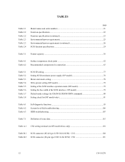
... page CHAPTER 1 GENERAL DESCRIPTION 13 1.1 Standard Features ...14 1.2 Hardware Structure ...18 1.3 System Configuration...19 CHAPTER 2 SPECIFICATIONS 21 2.1 Hardware Specifications 21 2.1.1 Model name and order number 21 2.1.2 Function specifications...22 2.1.3 Environmental specifications 25 2.1.4 Error rate ...26 2.1.5 Reliability ...27 2.2 SCSI Function Specifications 29 CHAPTER 3 ...47 4.1.2 Mounting orientations ...50 4.1.3 Notes on mounting ...50 4.2 Power Supply Requirements 53 4.3 Connection Requirements 58 4.3.1 SCA2 connector type 16-bit SCSI model (NC model 58 C141-E270 7
... page CHAPTER 1 GENERAL DESCRIPTION 13 1.1 Standard Features ...14 1.2 Hardware Structure ...18 1.3 System Configuration...19 CHAPTER 2 SPECIFICATIONS 21 2.1 Hardware Specifications 21 2.1.1 Model name and order number 21 2.1.2 Function specifications...22 2.1.3 Environmental specifications 25 2.1.4 Error rate ...26 2.1.5 Reliability ...27 2.2 SCSI Function Specifications 29 CHAPTER 3 ...47 4.1.2 Mounting orientations ...50 4.1.3 Notes on mounting ...50 4.2 Power Supply Requirements 53 4.3 Connection Requirements 58 4.3.1 SCA2 connector type 16-bit SCSI model (NC model 58 C141-E270 7

Product Manual
Page 12
4.3.2 4.3.3 4.3.4 68-pin connector type 16-bit SCSI model (NP model 60 Cable connector requirements 67 External operator panel (on NP model drives only 68 CHAPTER 5 INSTALLATION 71 5.1 Notes on Handling HDDs 71 5.2 Connections...73 5.3 Setting Terminals ...75 5.3.1 SCSI ID setting...76 5.3.2 Each mode setting ...78 5.3.3 Mode settings ......
4.3.2 4.3.3 4.3.4 68-pin connector type 16-bit SCSI model (NP model 60 Cable connector requirements 67 External operator panel (on NP model drives only 68 CHAPTER 5 INSTALLATION 71 5.1 Notes on Handling HDDs 71 5.2 Connections...73 5.3 Setting Terminals ...75 5.3.1 SCSI ID setting...76 5.3.2 Each mode setting ...78 5.3.3 Mode settings ......

Product Manual
Page 13
...), (B-44-xx), (B-47-xx), (B-48-00), (B-49-00), (B-4D-xx) and (B-4E-00): SCSI interface error 116 APPENDIX A SETTING TERMINALS 117 A.1 Setting Terminals (on NP model only 118 APPENDIX B CONNECTOR SIGNAL ALLOCATION 119 B.1 SCSI Connector Signal Allocation: SCA2 type LVD 16-bit SCSI 120 B.2 SCSI Connector Signal Allocation: 68-pin type...
...), (B-44-xx), (B-47-xx), (B-48-00), (B-49-00), (B-4D-xx) and (B-4E-00): SCSI interface error 116 APPENDIX A SETTING TERMINALS 117 A.1 Setting Terminals (on NP model only 118 APPENDIX B CONNECTOR SIGNAL ALLOCATION 119 B.1 SCSI Connector Signal Allocation: SCA2 type LVD 16-bit SCSI 120 B.2 SCSI Connector Signal Allocation: 68-pin type...

Product Manual
Page 14
... Figure 4.12 Figure 4.13 Figure 4.14 Figure 4.15 Figure 4.16 Figure 4.17 Figure 4.18 Figure 4.19 Figure 4.20 Figure 4.21 Figure 4.22 NC model dimensions...48 NP model dimensions ...49 HDD orientations...50 Mounting frame structure ...51 Limitation of side-mounting 52 Surface temperature measurement points 53 Current waveform (Spin-up 54...
... Figure 4.12 Figure 4.13 Figure 4.14 Figure 4.15 Figure 4.16 Figure 4.17 Figure 4.18 Figure 4.19 Figure 4.20 Figure 4.21 Figure 4.22 NC model dimensions...48 NP model dimensions ...49 HDD orientations...50 Mounting frame structure ...51 Limitation of side-mounting 52 Surface temperature measurement points 53 Current waveform (Spin-up 54...

Product Manual
Page 15
Figure 4.23 External operator panel circuit example 68 Figure 5.1 Figure 5.2 Figure 5.3 Figure 5.4 Figure 5.5 SCSI bus connections ...74 Setting terminals location (on NP models only 75 CN2 setting terminal (on NP models only 76 Checking the SCSI connection (A 85 Checking the SCSI connection (B 86 Figure 6.1 Figure 6.2 Figure 6.3 Figure 6.4 Test flowchart ...103 Single HDD packaging...108 Multi-box packaging...110 Fraction packaging ...111 Figure 7.1 Sense data format...114 C141-E270 11
Figure 4.23 External operator panel circuit example 68 Figure 5.1 Figure 5.2 Figure 5.3 Figure 5.4 Figure 5.5 SCSI bus connections ...74 Setting terminals location (on NP models only 75 CN2 setting terminal (on NP models only 76 Checking the SCSI connection (A 85 Checking the SCSI connection (B 86 Figure 6.1 Figure 6.2 Figure 6.3 Figure 6.4 Test flowchart ...103 Single HDD packaging...108 Multi-box packaging...110 Fraction packaging ...111 Figure 7.1 Sense data format...114 C141-E270 11
Product Manual
Page 16
......77 Setting SCSI terminator power supply (NP model 78 Motor start mode setting...78 Write protect setting (NP model 79 Setting of the SCSI interface operation mode (NP model 79 Setting the bus width of the SCSI interface (NP model 79 Default mode settings (by CHANGE DEFINITION ... functions ...95 System-level field troubleshooting 106 HDD troubleshooting ...107 Table 7.1 Definition of sense data ...115 Table A.1 CN2 setting terminal (on NP model drives only 118 Table B.1 Table B.2 SCSI connector (SCA2 type LVD 16-bit SCSI): CN1 120 SCSI connector (68-pin type LVD 16-bit SCSI...
......77 Setting SCSI terminator power supply (NP model 78 Motor start mode setting...78 Write protect setting (NP model 79 Setting of the SCSI interface operation mode (NP model 79 Setting the bus width of the SCSI interface (NP model 79 Default mode settings (by CHANGE DEFINITION ... functions ...95 System-level field troubleshooting 106 HDD troubleshooting ...107 Table 7.1 Definition of sense data ...115 Table A.1 CN2 setting terminal (on NP model drives only 118 Table B.1 Table B.2 SCSI connector (SCA2 type LVD 16-bit SCSI): CN1 120 SCSI connector (68-pin type LVD 16-bit SCSI...

Product Manual
Page 18
... ultra SCSI model, number of connectable SCSI devices on the same SCSI bus is varied as follows. • 8-bit SCSI: 8 drives max. (option for SCSI-2. 8-bit data bus is available only with the Restriction of the use of certain Hazardous Substances in the standard 3.5-inch hard disk drive form factor,... SCSI The HDD has 16-bit data bus width (16-bit SCSI), which have the wide transfer function suitable for NP model) • 16-bit SCSI: 16 drives max. 14 C141-E270 1.1 Standard Features (1) Compactness Since the SCSI controller circuit is extremely compact. This allows software to ...
... ultra SCSI model, number of connectable SCSI devices on the same SCSI bus is varied as follows. • 8-bit SCSI: 8 drives max. (option for SCSI-2. 8-bit data bus is available only with the Restriction of the use of certain Hazardous Substances in the standard 3.5-inch hard disk drive form factor,... SCSI The HDD has 16-bit data bus width (16-bit SCSI), which have the wide transfer function suitable for NP model) • 16-bit SCSI: 16 drives max. 14 C141-E270 1.1 Standard Features (1) Compactness Since the SCSI controller circuit is extremely compact. This allows software to ...

Product Manual
Page 24
The initiator selects one SCSI device by specifying that SCSI ID, then specifies the LUN to select the peripheral device for NP model, switch selectable) 16-bit SCSI:Selectable from 0 to 7 (option for input/output operation. Using disconnect/reconnect function, concurrent input/output processing is addressed...: 8-bit SCSI:Selectable from 0 to 15 (switch selectable) 0 (fixed) 20 C141-E270 The HDD is constructed so that the whole volume of disk drive is assigned for the 16-bit SCSI in any combination. For example, the system can be configured as multi-host system on the bus has...
The initiator selects one SCSI device by specifying that SCSI ID, then specifies the LUN to select the peripheral device for NP model, switch selectable) 16-bit SCSI:Selectable from 0 to 7 (option for input/output operation. Using disconnect/reconnect function, concurrent input/output processing is addressed...: 8-bit SCSI:Selectable from 0 to 15 (switch selectable) 0 (fixed) 20 C141-E270 The HDD is constructed so that the whole volume of disk drive is assigned for the 16-bit SCSI in any combination. For example, the system can be configured as multi-host system on the bus has...

Product Manual
Page 25
...specifications of the SCSI. 2.1 Hardware Specifications 2.1.1 Model name and order number Each model has a different recording capacities and interface connector type when shipped. Table 2.1 lists the model name and order number. The data format ...Model names and order numbers Model name Order number SCSI type MBA3300NC MBA3300NP MBA3147NC MBA3147NP MBA3073NC MBA3073NP CA06708-B400 CA06708-B850 CA06708-B200 CA06708-B650 CA06708-B100 CA06708-B550 SCA2, LVD 68-pin, LVD SCA2, LVD 68-pin, LVD SCA2, LVD 68-pin, LVD Capacity (user area) 300 GB (*) 147 GB (*) 73.5 GB (*) (*) One gigabyte (GB...
...specifications of the SCSI. 2.1 Hardware Specifications 2.1.1 Model name and order number Each model has a different recording capacities and interface connector type when shipped. Table 2.1 lists the model name and order number. The data format ...Model names and order numbers Model name Order number SCSI type MBA3300NC MBA3300NP MBA3147NC MBA3147NP MBA3073NC MBA3073NP CA06708-B400 CA06708-B850 CA06708-B200 CA06708-B650 CA06708-B100 CA06708-B550 SCA2, LVD 68-pin, LVD SCA2, LVD 68-pin, LVD SCA2, LVD 68-pin, LVD Capacity (user area) 300 GB (*) 147 GB (*) 73.5 GB (*) (*) One gigabyte (GB...

Product Manual
Page 33
...where the terminating resistor is mounted on the PCA × TERMPWR signal send function Ο (NP model) Connector 68-pin P cable connector 80-pin SCA2 connector Ο (NP model) Ο (NC model) Data bus parity (Data bus CRC) Ο Bus arbitration function Ο Disconnection/reconnection function ... (Single-ended or LVD) changes automatically by Diffsence signal level. (*2) 1MB/s=1,000,000 bytes/s (*3) 1MB=1,048,576 bytes (*4) Refer to #15 (Jumper selection, NP model) #0 fixed Ο 20 MB/s max. Ο 40 MB/s max. Ο 40 MB/s max. Ο 80 MB/s max. Ο 160 MB/s...
...where the terminating resistor is mounted on the PCA × TERMPWR signal send function Ο (NP model) Connector 68-pin P cable connector 80-pin SCA2 connector Ο (NP model) Ο (NC model) Data bus parity (Data bus CRC) Ο Bus arbitration function Ο Disconnection/reconnection function ... (Single-ended or LVD) changes automatically by Diffsence signal level. (*2) 1MB/s=1,000,000 bytes/s (*3) 1MB=1,048,576 bytes (*4) Refer to #15 (Jumper selection, NP model) #0 fixed Ο 20 MB/s max. Ο 40 MB/s max. Ο 40 MB/s max. Ο 80 MB/s max. Ο 160 MB/s...

Product Manual
Page 42
... actual capacity depends on the operating environment and formatting. Table 3.1 Format capacity Model Data block length User blocks Format capacity MBA3300NC, MBA3300NP 585,937,500 300 GB (*) MBA3147NC, MBA3147NP 512 287,277,984 147 GB (*) MBA3073NC, MBA3073NP 143,638,992 73.5 GB (*) (*) One gigabyte (GB) = one billion bytes; The initiator specifies the data to calculate the format...
... actual capacity depends on the operating environment and formatting. Table 3.1 Format capacity Model Data block length User blocks Format capacity MBA3300NC, MBA3300NP 585,937,500 300 GB (*) MBA3147NC, MBA3147NP 512 287,277,984 147 GB (*) MBA3073NC, MBA3073NP 143,638,992 73.5 GB (*) (*) One gigabyte (GB) = one billion bytes; The initiator specifies the data to calculate the format...

Product Manual
Page 52
The value marked with (*) indicates the dimension between mounting holes on the bottom face. [Unit: mm] Figure 4.1 NC model dimensions 48 C141-E270
The value marked with (*) indicates the dimension between mounting holes on the bottom face. [Unit: mm] Figure 4.1 NC model dimensions 48 C141-E270

Product Manual
Page 53
The value marked with (*) indicates the dimension between mounting holes on the bottom face. [Unit: mm] Figure 4.2 NP model dimensions C141-E270 49
The value marked with (*) indicates the dimension between mounting holes on the bottom face. [Unit: mm] Figure 4.2 NP model dimensions C141-E270 49

Product Manual
Page 61
... Issue START/STOP commands at the AC input terminal on the HDD power supply unit. For the NC model drives, the spindle motors should be designed with a setting terminal on the HDD (NP model only). SCSI ID 0 1 2... 15 Delay time of power supply to the terminating resistor is selected ...VDC line when the spindle motor rotation starts. s 180 s (5) Power supply to SCSI terminating resistor If power for this selection. For the NP model drives, the spindle motors should be installed at more to start control mode, see Subsection 5.3.2. b) Turn on the +12V DC power in Figure 4.12 ...
... Issue START/STOP commands at the AC input terminal on the HDD power supply unit. For the NC model drives, the spindle motors should be designed with a setting terminal on the HDD (NP model only). SCSI ID 0 1 2... 15 Delay time of power supply to the terminating resistor is selected ...VDC line when the spindle motor rotation starts. s 180 s (5) Power supply to SCSI terminating resistor If power for this selection. For the NP model drives, the spindle motors should be installed at more to start control mode, see Subsection 5.3.2. b) Turn on the +12V DC power in Figure 4.12 ...

Product Manual
Page 62
SCSI connector (CN1) (including power supply) Figure 4.13 NC connectors location 58 C141-E270 Figure 4.12 AC noise filter (recommended) 4.3 Connection Requirements 4.3.1 SCA2 connector type 16-bit SCSI model (NC model) (1) Connectors Figure 4.13 shows the locations of connectors on the SCA2 connector type 16-bit SCSI model (NC model).
SCSI connector (CN1) (including power supply) Figure 4.13 NC connectors location 58 C141-E270 Figure 4.12 AC noise filter (recommended) 4.3 Connection Requirements 4.3.1 SCA2 connector type 16-bit SCSI model (NC model) (1) Connectors Figure 4.13 shows the locations of connectors on the SCA2 connector type 16-bit SCSI model (NC model).

Product Manual
Page 63
... B.1 in the SCSI connector. Figure 4.14 SCA2 type 16-bit SCSI connector (3) Connector for external operator panel This connector is included in Appendix B for NC model drives. Figure 4.14 shows the SCSI connector. For details on the connector. The power connector is not available for signal assignments on the physical/electrical requirements...
... B.1 in the SCSI connector. Figure 4.14 SCA2 type 16-bit SCSI connector (3) Connector for external operator panel This connector is included in Appendix B for NC model drives. Figure 4.14 shows the SCSI connector. For details on the connector. The power connector is not available for signal assignments on the physical/electrical requirements...

Product Manual
Page 64
4.3.2 68-pin connector type 16-bit SCSI model (NP model) (1) Connectors Figures 4.15 show the locations of the SCSI Physical Interface Specifications. 60 C141-E270 For details on the physical/electrical requirements of the interface... SCSI connector. Figure 4.16 shows the SCSI connector. See Section B.2 in Appendix B for the signal assignments on the 68-pin connector type 16-bit SCSI model (NP model). • Power supply connector • SCSI connector • External operator panel connector External operator panel connector (CN2) Power supply connector (CN1) External operator ...
4.3.2 68-pin connector type 16-bit SCSI model (NP model) (1) Connectors Figures 4.15 show the locations of the SCSI Physical Interface Specifications. 60 C141-E270 For details on the physical/electrical requirements of the interface... SCSI connector. Figure 4.16 shows the SCSI connector. See Section B.2 in Appendix B for the signal assignments on the 68-pin connector type 16-bit SCSI model (NP model). • Power supply connector • SCSI connector • External operator panel connector External operator panel connector (CN2) Power supply connector (CN1) External operator ...

Product Manual
Page 71
...when SG and FG are connected in the system, it is provided with the HDD. Table 4.2 Recommended components for connection Applicable model Type Name NC SCSI connector (CN1) Connector Part number (Size) 787311-4 71743-1085 Manufacturer Tyco Electronics AMP Reference (*1) Molex...panel (CN1) Contact A3B-2630SCC HIROSE ELECTRIC S3 Cable (AWG26 to 36) Cable socket housing FCN-723J024/2M FUJITSU TAKAMIZAWA External operator panel (CN2) Contact FCN-723J-G/AM FUJITSU TAKAMIZAWA S4 Cable (AWG28) (*1) See Figure 4.22. (1) SCSI cable Refer to Section 1.3 "Physical Requirements"...
...when SG and FG are connected in the system, it is provided with the HDD. Table 4.2 Recommended components for connection Applicable model Type Name NC SCSI connector (CN1) Connector Part number (Size) 787311-4 71743-1085 Manufacturer Tyco Electronics AMP Reference (*1) Molex...panel (CN1) Contact A3B-2630SCC HIROSE ELECTRIC S3 Cable (AWG26 to 36) Cable socket housing FCN-723J024/2M FUJITSU TAKAMIZAWA External operator panel (CN2) Contact FCN-723J-G/AM FUJITSU TAKAMIZAWA S4 Cable (AWG28) (*1) See Figure 4.22. (1) SCSI cable Refer to Section 1.3 "Physical Requirements"...

