
Product Manual
Page 5
... information for installing the disk drives. This manual details the specifications and functions of the above disk drives, and gives the requirements and procedures for users who have a basic understanding of troubleshooting the disk drives. CHAPTER 2 SPECIFICATIONS This chapter gives detailed specifications of interface connector. This manual is written for installing it into a host computer system. This chapter also describes diagnostic methods for setting device number and operation modes, mounting the disk drive, connecting the cables, and confirming drive operation...
... information for installing the disk drives. This manual details the specifications and functions of the above disk drives, and gives the requirements and procedures for users who have a basic understanding of troubleshooting the disk drives. CHAPTER 2 SPECIFICATIONS This chapter gives detailed specifications of interface connector. This manual is written for installing it into a host computer system. This chapter also describes diagnostic methods for setting device number and operation modes, mounting the disk drive, connecting the cables, and confirming drive operation...
Product Manual
Page 7
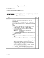
... this manual are used, inserting the cables in the wrong direction can be careful of the connection position of the cable. Data loss 1. Do not change the setting of terminals except following setting pins during operation and remain hot immediately after turning off before connecting or disconnecting 82 cables. 2. The user must not change setting status set at factory shipment. 2. Check that system power is turned on .(except NC model...
... this manual are used, inserting the cables in the wrong direction can be careful of the connection position of the cable. Data loss 1. Do not change the setting of terminals except following setting pins during operation and remain hot immediately after turning off before connecting or disconnecting 82 cables. 2. The user must not change setting status set at factory shipment. 2. Check that system power is turned on .(except NC model...

Product Manual
Page 11
...3 DATA FORMAT 31 3.1 Data Space...31 3.1.1 Cylinder configuration ...31 3.1.2 Alternate spare area ...33 3.1.3 Track format...35 3.1.4 Sector format ...36 3.1.5 Format capacity ...38 3.2 Logical Data Block Addressing 38 3.3 Defect Management ...40 3.3.1 Defect list ...40 3.3.2 Alternate block allocation 40 CHAPTER 4 INSTALLATION REQUIREMENTS 47 4.1 Mounting Requirements 47 4.1.1 External dimensions ...47 4.1.2 Mounting orientations ...50 4.1.3 Notes on mounting ...50 4.2 Power Supply Requirements 53 4.3 Connection Requirements 58 4.3.1 SCA2 connector type 16-bit SCSI model (NC model 58...
...3 DATA FORMAT 31 3.1 Data Space...31 3.1.1 Cylinder configuration ...31 3.1.2 Alternate spare area ...33 3.1.3 Track format...35 3.1.4 Sector format ...36 3.1.5 Format capacity ...38 3.2 Logical Data Block Addressing 38 3.3 Defect Management ...40 3.3.1 Defect list ...40 3.3.2 Alternate block allocation 40 CHAPTER 4 INSTALLATION REQUIREMENTS 47 4.1 Mounting Requirements 47 4.1.1 External dimensions ...47 4.1.2 Mounting orientations ...50 4.1.3 Notes on mounting ...50 4.2 Power Supply Requirements 53 4.3 Connection Requirements 58 4.3.1 SCA2 connector type 16-bit SCSI model (NC model 58...

Product Manual
Page 12
... 68-pin connector type 16-bit SCSI model (NP model 60 Cable connector requirements 67 External operator panel (on NP model drives only 68 CHAPTER 5 INSTALLATION 71 5.1 Notes on Handling HDDs 71 5.2 Connections...73 5.3 Setting Terminals ...75 5.3.1 SCSI ID setting...76 5.3.2 Each mode setting ...78 5.3.3 Mode settings ...80 5.4 Mounting HDDs...81 5.4.1 Check before mounting ...81 5.4.2 Mounting procedures...81 5.5 Connecting Cables...82 5.6 Checking Operation after Installation and Preparing the HDDs for Use 83 5.6.1 Confirming initial operations 83 5.6.2 Checking SCSI connection 84...
... 68-pin connector type 16-bit SCSI model (NP model 60 Cable connector requirements 67 External operator panel (on NP model drives only 68 CHAPTER 5 INSTALLATION 71 5.1 Notes on Handling HDDs 71 5.2 Connections...73 5.3 Setting Terminals ...75 5.3.1 SCSI ID setting...76 5.3.2 Each mode setting ...78 5.3.3 Mode settings ...80 5.4 Mounting HDDs...81 5.4.1 Check before mounting ...81 5.4.2 Mounting procedures...81 5.5 Connecting Cables...82 5.6 Checking Operation after Installation and Preparing the HDDs for Use 83 5.6.1 Confirming initial operations 83 5.6.2 Checking SCSI connection 84...

Product Manual
Page 14
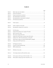
... sequence (2 56 Power on/off sequence (3 56 AC noise filter (recommended 58 NC connectors location ...58 SCA2 type 16-bit SCSI connector 59 NP connectors and terminals location 60 68-pin type 16-bit SCSI interface connector 61 Power supply connector (68-pin type 16-bit SCSI 61 External operator panel connector (CN1 62 External operator panel connector (CN2 62 16-bit SCSI ID external input 63 Output signal for external LED 65 SCSI cables connection ...66 10 C141...
... sequence (2 56 Power on/off sequence (3 56 AC noise filter (recommended 58 NC connectors location ...58 SCA2 type 16-bit SCSI connector 59 NP connectors and terminals location 60 68-pin type 16-bit SCSI interface connector 61 Power supply connector (68-pin type 16-bit SCSI 61 External operator panel connector (CN1 62 External operator panel connector (CN2 62 16-bit SCSI ID external input 63 Output signal for external LED 65 SCSI cables connection ...66 10 C141...
Product Manual
Page 16
... setting...77 Setting SCSI terminator power supply (NP model 78 Motor start mode setting...78 Write protect setting (NP model 79 Setting of the SCSI interface operation mode (NP model 79 Setting the bus width of the SCSI interface (NP model 79 Default mode settings (by CHANGE DEFINITION command 80 Setting check list (NP model only 81 Table 6.1 Table 6.2 Table 6.3 Self-diagnostic functions ...95 System-level field troubleshooting 106 HDD troubleshooting ...107 Table 7.1 Definition of sense data ...115 Table A.1 CN2 setting terminal (on NP model drives...
... setting...77 Setting SCSI terminator power supply (NP model 78 Motor start mode setting...78 Write protect setting (NP model 79 Setting of the SCSI interface operation mode (NP model 79 Setting the bus width of the SCSI interface (NP model 79 Default mode settings (by CHANGE DEFINITION command 80 Setting check list (NP model only 81 Table 6.1 Table 6.2 Table 6.3 Self-diagnostic functions ...95 System-level field troubleshooting 106 HDD troubleshooting ...107 Table 7.1 Definition of sense data ...115 Table A.1 CN2 setting terminal (on NP model drives...
Product Manual
Page 30
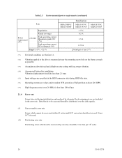
... default on retry setting with log sweep vibration. (*4) At power-off state after installation Vibration displacement should be less than 2.5 mm. (*5) Input voltages are specified at the HDD connector side during HDD Idle state. (*6) Operating currents are values under random W/R operation of full partition at near the mounting screw hole on the frame as much as possible. (*3) At random seek write/read . (2) Positioning error rate Positioning errors...
... default on retry setting with log sweep vibration. (*4) At power-off state after installation Vibration displacement should be less than 2.5 mm. (*5) Input voltages are specified at the HDD connector side during HDD Idle state. (*6) Operating currents are values under random W/R operation of full partition at near the mounting screw hole on the frame as much as possible. (*3) At random seek write/read . (2) Positioning error rate Positioning errors...
Product Manual
Page 31
... as low as follows. Note: The MTBF is defined as: MTBF= Operating time (hours) at case DE surface temperature above 50°C may degrade product reliability. Therefore, the user must design the system cabinet so that requires repair, adjustments, or replacement. Mishandling by the operator, failures due to bad environmental conditions, power trouble, host system trouble, cable failures, or other failures not caused by the equipment are not...
... as low as follows. Note: The MTBF is defined as: MTBF= Operating time (hours) at case DE surface temperature above 50°C may degrade product reliability. Therefore, the user must design the system cabinet so that requires repair, adjustments, or replacement. Mishandling by the operator, failures due to bad environmental conditions, power trouble, host system trouble, cable failures, or other failures not caused by the equipment are not...

Product Manual
Page 42
... sectors is accessed in logical data block units. accessible capacity will be accessed using the logical data block address of the spare sector area. Table 3.1 Format capacity Model Data block length User blocks Format capacity MBA3300NC, MBA3300NP 585,937,500 300 GB (*) MBA3147NC, MBA3147NP 512 287,277,984 147 GB (*) MBA3073NC, MBA3073NP 143,638,992 73.5 GB (*) (*) One gigabyte (GB) = one billion bytes; 3.1.5 Format capacity The size of the usable area for storing user data on the HDD (format capacity...
... sectors is accessed in logical data block units. accessible capacity will be accessed using the logical data block address of the spare sector area. Table 3.1 Format capacity Model Data block length User blocks Format capacity MBA3300NC, MBA3300NP 585,937,500 300 GB (*) MBA3147NC, MBA3147NP 512 287,277,984 147 GB (*) MBA3073NC, MBA3073NP 143,638,992 73.5 GB (*) (*) One gigabyte (GB) = one billion bytes; 3.1.5 Format capacity The size of the usable area for storing user data on the HDD (format capacity...
Product Manual
Page 49
... times AWRE (Type 2) =Maximum number which will be processed within pre-determined retry number (specified in this WRITE commands are logically continual and stored in automatic alternate block allocation during the execution of the READ or READ EXTENDED command. Remark: When a write protection is prohibited through the setting terminal, the auto alternate block allocation processing specification is rewritten and verified in Cache, - Write offtrack error...
... times AWRE (Type 2) =Maximum number which will be processed within pre-determined retry number (specified in this WRITE commands are logically continual and stored in automatic alternate block allocation during the execution of the READ or READ EXTENDED command. Remark: When a write protection is prohibited through the setting terminal, the auto alternate block allocation processing specification is rewritten and verified in Cache, - Write offtrack error...

Product Manual
Page 75
... Handling HDDs 5.2 Connections 5.3 Setting Terminals 5.4 Mounting HDDs 5.5 Connecting Cables 5.6 Checking Operation after Installation and Preparing the HDDs for Use 5.7 Dismounting HDDs This chapter describes the notes on handling HDDs, connections, setting switches and plugs, mounting HDDs, connecting cables, confirming drive operations after installation and preparation for use, and dismounting HDDs. 5.1 Notes on the PCBAs except setting terminal (CN1 and CN2). Do not touch any components on Handling HDDs The items listed in the specifications in...
... Handling HDDs 5.2 Connections 5.3 Setting Terminals 5.4 Mounting HDDs 5.5 Connecting Cables 5.6 Checking Operation after Installation and Preparing the HDDs for Use 5.7 Dismounting HDDs This chapter describes the notes on handling HDDs, connections, setting switches and plugs, mounting HDDs, connecting cables, confirming drive operations after installation and preparation for use, and dismounting HDDs. 5.1 Notes on the PCBAs except setting terminal (CN1 and CN2). Do not touch any components on Handling HDDs The items listed in the specifications in...

Product Manual
Page 76
... the requirements specified in Subsection 2.1.3 when the HDD is recommended to connect or disconnect connections when power is free from the HDD. For the carrying direction at delivery, use the same cushions and packages as a wooden desk. (2) Unpackaging a) Use a flat work for replacing. (4) Packaging a) Store the HDD in CN2. (NP model) b) Do not move the HDD when power is turned on or until the...
... the requirements specified in Subsection 2.1.3 when the HDD is recommended to connect or disconnect connections when power is free from the HDD. For the carrying direction at delivery, use the same cushions and packages as a wooden desk. (2) Unpackaging a) Use a flat work for replacing. (4) Packaging a) Store the HDD in CN2. (NP model) b) Do not move the HDD when power is turned on or until the...
Product Manual
Page 79
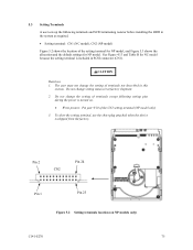
... setting terminal, use the short plug attached when the device is shipped from the factory. CAUTION Data loss 1. Do not change the setting of terminals not described in SCSI connector (CN1). Do not change setting status set at factory shipment. 2. 5.3 Setting Terminals A user sets up the following setting pins during the power is turned on NP models only) C141-E270 75 Pin 2 CN2 Pin 24 Pin 1 Pin 23 Figure 5.2 Setting terminals location (on . • Write protect: Pin...
... setting terminal, use the short plug attached when the device is shipped from the factory. CAUTION Data loss 1. Do not change the setting of terminals not described in SCSI connector (CN1). Do not change setting status set at factory shipment. 2. 5.3 Setting Terminals A user sets up the following setting pins during the power is turned on NP models only) C141-E270 75 Pin 2 CN2 Pin 24 Pin 1 Pin 23 Figure 5.2 Setting terminals location (on . • Write protect: Pin...
Product Manual
Page 91
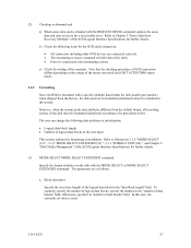
... ATTENTION report mode. 5.6.3 Formatting Since the HDD is formatted with a specific (default) data format for a recoverable error. Note that the checking procedure of SCSI connection differs depending on the setting of the disk must be obtained with the MODE SELECT or MODE SELECT EXTENDED command. The parameters are connected correctly. • The terminating resistor is used. Otherwise, specify 0 in "number of the cable. • Power is installed in the system. In this case, the currently set value...
... ATTENTION report mode. 5.6.3 Formatting Since the HDD is formatted with a specific (default) data format for a recoverable error. Note that the checking procedure of SCSI connection differs depending on the setting of the disk must be obtained with the MODE SELECT or MODE SELECT EXTENDED command. The parameters are connected correctly. • The terminating resistor is used. Otherwise, specify 0 in "number of the cable. • Power is installed in the system. In this case, the currently set value...

Product Manual
Page 93
... 3.1.6 "MODE SELECT EXTENDED (55)"of the SCSI Logical Interface Specifications for further details of the MODE SELECT and MODE SELECT EXTENDED commands and specifying the parameters. When the HDD, to the saved parameter value if the saving operation is executed from the initiator. This enables the HDD to the default value of each parameter 2. For example, even if the initialization of the disk is not executed. 5.6.4 Setting parameters The user can be changed...
... 3.1.6 "MODE SELECT EXTENDED (55)"of the SCSI Logical Interface Specifications for further details of the MODE SELECT and MODE SELECT EXTENDED commands and specifying the parameters. When the HDD, to the saved parameter value if the saving operation is executed from the initiator. This enables the HDD to the default value of each parameter 2. For example, even if the initialization of the disk is not executed. 5.6.4 Setting parameters The user can be changed...
Product Manual
Page 95
Refer to transfer data on the SCSI bus at a read (READ or READ EXTENDED command) or write operation (WRITE, WRITE EXTENDED, or WRITE AND VERIFY command) of the disk. C141-E270 91 However, it is recommended to be specified. 2. It is recommended to use the default setting in normal operations. (2) Disconnection/reconnection parameters (page code = 2) The following parameters are used to optimize the start timing of reconnection processing to Chapter 2 "Data Buffer Management" of the...
Refer to transfer data on the SCSI bus at a read (READ or READ EXTENDED command) or write operation (WRITE, WRITE EXTENDED, or WRITE AND VERIFY command) of the disk. C141-E270 91 However, it is recommended to be specified. 2. It is recommended to use the default setting in normal operations. (2) Disconnection/reconnection parameters (page code = 2) The following parameters are used to optimize the start timing of reconnection processing to Chapter 2 "Data Buffer Management" of the...
Product Manual
Page 105
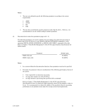
...done by the user, retail dealer, distributor, or OEM engineer. (2) Factory maintenance (parts replacement) • This replacement can only be included: a) HDD model, part number (P/N), revision number, serial number (S/N), and date of manufacturing b) Error status • Date when the error occurred • System configuration • Environmental conditions (temperature, humidity, and voltage) c) Error history d) Error contents • Outline of inconvenience • Issued commands and specified parameters • Sense data • Other error analysis information See Section 5.1 for...
...done by the user, retail dealer, distributor, or OEM engineer. (2) Factory maintenance (parts replacement) • This replacement can only be included: a) HDD model, part number (P/N), revision number, serial number (S/N), and date of manufacturing b) Error status • Date when the error occurred • System configuration • Environmental conditions (temperature, humidity, and voltage) c) Error history d) Error contents • Outline of inconvenience • Issued commands and specified parameters • Sense data • Other error analysis information See Section 5.1 for...

Product Manual
Page 110
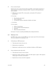
... NC model, check the voltage between pin 1 and 2 of the SCSI connector. For NC model, check the voltage between the disk drive and controller. Interface cable connection Check that the SCSI interface cable is correctly connected between pin 36 and 76 of the power connector. See Section 5.3. For NP model, check the voltage between pin 3 and 4 of a possible fault. Intermittent or nonfatal errors Check the AC voltage from 11.4 to the hardware and software manuals supplied with the...
... NC model, check the voltage between pin 1 and 2 of the SCSI connector. For NC model, check the voltage between the disk drive and controller. Interface cable connection Check that the SCSI interface cable is correctly connected between pin 36 and 76 of the power connector. See Section 5.3. For NP model, check the voltage between pin 3 and 4 of a possible fault. Intermittent or nonfatal errors Check the AC voltage from 11.4 to the hardware and software manuals supplied with the...

Product Manual
Page 132
... maintenance 101 finding possibly faulty part 108 format capacity 38 format parameter 88 FORMAT UNIT command 88 formatting 87 G gaps 37 general note 71 H hardware function test 96 hardware structure 18 HDD replacement 101 HDD troubleshooting 107 head 18 head skew 35 high speed data transfer 15 high speed positioning 17 I initial seek operation check 104 initial self-diagnostic 96 installation 71, 72 installation requirement 47 interface test 99 internal test space 33 L large capacity 17 leak magnetic flux...
... maintenance 101 finding possibly faulty part 108 format capacity 38 format parameter 88 FORMAT UNIT command 88 formatting 87 G gaps 37 general note 71 H hardware function test 96 hardware structure 18 HDD replacement 101 HDD troubleshooting 107 head 18 head skew 35 high speed data transfer 15 high speed positioning 17 I initial seek operation check 104 initial self-diagnostic 96 installation 71, 72 installation requirement 47 interface test 99 internal test space 33 L large capacity 17 leak magnetic flux...

Product Manual
Page 133
... type SCSI connector 59 SCSI bus configuration 20 SCSI bus connection 74 SCSI cable connection 66 SCSI connector 120, 121 SCSI connector signal allocation............120, 121 SCSI function specification 29 SCSI ID setting 76, 77 SCSI interface error 116 SCSI standard 14 sector format 36 seek test 96 self-diagnostic 95 self-diagnostic function 95 SEND DIAGNOSTIC command 97 sense data 113, 116 sense data analysis 115 sense data collection 113 sense data format 114 sense key 113 service life 100 service system 101 setting bus width of SCSI interface...
... type SCSI connector 59 SCSI bus configuration 20 SCSI bus connection 74 SCSI cable connection 66 SCSI connector 120, 121 SCSI connector signal allocation............120, 121 SCSI function specification 29 SCSI ID setting 76, 77 SCSI interface error 116 SCSI standard 14 sector format 36 seek test 96 self-diagnostic 95 self-diagnostic function 95 SEND DIAGNOSTIC command 97 sense data 113, 116 sense data analysis 115 sense data collection 113 sense data format 114 sense key 113 service life 100 service system 101 setting bus width of SCSI interface...


