Product Manual
Page 12
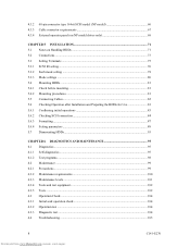
... (NP model 60 Cable connector requirements 67 External operator panel (on NP model drives only 68 CHAPTER 5 INSTALLATION 71 5.1 Notes on Handling HDDs 71 5.2 Connections...73 5.3 Setting Terminals ...75 5.3.1 SCSI ID setting...76 5.3.2 Each mode setting ...78 5.3.3 Mode settings ...80 5.4 Mounting HDDs...81 5.4.1 Check before mounting ...81 5.4.2 Mounting procedures...81 5.5 Connecting Cables...82 5.6 Checking...
... (NP model 60 Cable connector requirements 67 External operator panel (on NP model drives only 68 CHAPTER 5 INSTALLATION 71 5.1 Notes on Handling HDDs 71 5.2 Connections...73 5.3 Setting Terminals ...75 5.3.1 SCSI ID setting...76 5.3.2 Each mode setting ...78 5.3.3 Mode settings ...80 5.4 Mounting HDDs...81 5.4.1 Check before mounting ...81 5.4.2 Mounting procedures...81 5.5 Connecting Cables...82 5.6 Checking...

Product Manual
Page 14
... type 16-bit SCSI connector 59 NP connectors and terminals location 60 68-pin type 16-bit SCSI interface connector 61 Power supply connector (68-pin type 16-bit SCSI 61 External operator panel connector (CN1 62 External operator panel connector (CN2 62 16-bit SCSI ID external input 63 Output... signal for external LED 65 SCSI cables connection ...66 10 Downloaded...
... type 16-bit SCSI connector 59 NP connectors and terminals location 60 68-pin type 16-bit SCSI interface connector 61 Power supply connector (68-pin type 16-bit SCSI 61 External operator panel connector (CN1 62 External operator panel connector (CN2 62 16-bit SCSI ID external input 63 Output... signal for external LED 65 SCSI cables connection ...66 10 Downloaded...
Product Manual
Page 16
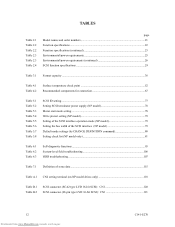
... 5.1 Table 5.2 Table 5.3 Table 5.4 Table 5.5 Table 5.6 Table 5.7 Table 5.8 SCSI ID setting...77 Setting SCSI terminator power supply (NP model 78 Motor start mode setting...78 Write protect setting (NP model 79 Setting of the SCSI interface operation mode (NP model 79 Setting the bus width of the...Definition of sense data ...115 Table A.1 CN2 setting terminal (on NP model drives only 118 Table B.1 Table B.2 SCSI connector (SCA2 type LVD 16-bit SCSI): CN1 120 SCSI connector (68-pin type LVD 16-bit SCSI): CN1 121 12 Downloaded from www.Manualslib.com manuals search engine C141-E270
... 5.1 Table 5.2 Table 5.3 Table 5.4 Table 5.5 Table 5.6 Table 5.7 Table 5.8 SCSI ID setting...77 Setting SCSI terminator power supply (NP model 78 Motor start mode setting...78 Write protect setting (NP model 79 Setting of the SCSI interface operation mode (NP model 79 Setting the bus width of the...Definition of sense data ...115 Table A.1 CN2 setting terminal (on NP model drives only 118 Table B.1 Table B.2 SCSI connector (SCA2 type LVD 16-bit SCSI): CN1 120 SCSI connector (68-pin type LVD 16-bit SCSI): CN1 121 12 Downloaded from www.Manualslib.com manuals search engine C141-E270
Product Manual
Page 24
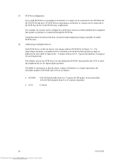
...input/output operation. The HDD is possible on multiSCSI devices. (2) Addressing of SCSI ID and LUN are as follows: • SCSI ID: • LUN: 8-bit SCSI:Selectable from 0 to 7 (option for NP model, switch selectable) 16-bit SCSI:Selectable from 0 to 15 (switch selectable) 0 (fixed) 20 Downloaded ... the bus has its own unique address (SCSI ID:#n in Figure 1.1). The initiator selects one SCSI device by specifying that the whole volume of disk drive is a single logical unit, the selectable number of peripheral device Each SCSI device on which multiple host computers that operates...
...input/output operation. The HDD is possible on multiSCSI devices. (2) Addressing of SCSI ID and LUN are as follows: • SCSI ID: • LUN: 8-bit SCSI:Selectable from 0 to 7 (option for NP model, switch selectable) 16-bit SCSI:Selectable from 0 to 15 (switch selectable) 0 (fixed) 20 Downloaded ... the bus has its own unique address (SCSI ID:#n in Figure 1.1). The initiator selects one SCSI device by specifying that the whole volume of disk drive is a single logical unit, the selectable number of peripheral device Each SCSI device on which multiple host computers that operates...
Product Manual
Page 33
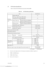
...MB/s max. C141-E270 29 Downloaded from www.Manualslib.com manuals search engine 2.2 SCSI Function Specifications Table 2.4 shows the SCSI functions provided with the HDD. Table 2.4 SCSI function specifications Item Specification Single-ended type Ο HVD type (High Voltage Differential)...927; Bus arbitration function Ο Disconnection/reconnection function Ο Addressing SCSI ID 16-bit SCSI LUN (logical unit number) 8-bit SCSI (Single-ended type) Data transfer (Synchronous mode) (*2) (Ultra 2 type) 16-bit SCSI (Single-ended type) (Ultra 2 Wide type) (U160 LVD type)...
...MB/s max. C141-E270 29 Downloaded from www.Manualslib.com manuals search engine 2.2 SCSI Function Specifications Table 2.4 shows the SCSI functions provided with the HDD. Table 2.4 SCSI function specifications Item Specification Single-ended type Ο HVD type (High Voltage Differential)...927; Bus arbitration function Ο Disconnection/reconnection function Ο Addressing SCSI ID 16-bit SCSI LUN (logical unit number) 8-bit SCSI (Single-ended type) Data transfer (Synchronous mode) (*2) (Ultra 2 type) 16-bit SCSI (Single-ended type) (Ultra 2 Wide type) (U160 LVD type)...
Product Manual
Page 61
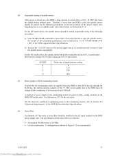
...on the HDD power supply unit. Therefore, if more at the AC input terminal on to start control mode, see Subsection 5.3.2. SCSI ID 0 1 2... 15 Delay time of spindle motor starting of spindle motors After power is selected with considering of an increase of ...drives, the spindle motors should be started after a delay of this noise filter is recommended. C141-E270 57 Downloaded from the HDD to other SCSI devices through the SCSI bus, the current-carrying capacity of supplying power to the terminating resistor, refer to 200 mA. The specification of 12 seconds times [SCSI ID...
...on the HDD power supply unit. Therefore, if more at the AC input terminal on to start control mode, see Subsection 5.3.2. SCSI ID 0 1 2... 15 Delay time of spindle motor starting of spindle motors After power is selected with considering of an increase of ...drives, the spindle motors should be started after a delay of this noise filter is recommended. C141-E270 57 Downloaded from the HDD to other SCSI devices through the SCSI bus, the current-carrying capacity of supplying power to the terminating resistor, refer to 200 mA. The specification of 12 seconds times [SCSI ID...

Product Manual
Page 65
...Figure 4.17 shows the shape and the terminal arrangement of the output connector of an external LED on the front panel, and an SCSI ID setting switch. For the recommended circuit of the external operator panel, see Subsection 4.3.4. Also, a connector for the external operator panel ...are provided on the power supply side. (4) Connector for external operator panel • Connector for 16-bit SCSI external operator panel CN1 provides connector for DC grounding. Therefore, when connecting SG and FG in the system, use the +5 VDC RETURN (ground...
...Figure 4.17 shows the shape and the terminal arrangement of the output connector of an external LED on the front panel, and an SCSI ID setting switch. For the recommended circuit of the external operator panel, see Subsection 4.3.4. Also, a connector for the external operator panel ...are provided on the power supply side. (4) Connector for external operator panel • Connector for 16-bit SCSI external operator panel CN1 provides connector for DC grounding. Therefore, when connecting SG and FG in the system, use the +5 VDC RETURN (ground...

Product Manual
Page 67
Figure 4.20 16-bit SCSI ID external input C141-E270 63 Downloaded from www.Manualslib.com manuals search engine For the recommended circuit examples, see Subsection 4.3.4. (5) External operator panel connector Signals a. 16-bit SCSI -ID3, -ID2, -ID1, -ID0: Input signals (CN1-A1, A3, A5, A7 pin and CN2-02, 04, 06, 08 pin) These signals are used for providing switches to set the SCSI ID of the HDD externally. Figure 4.20 shows the electrical requirements.
Figure 4.20 16-bit SCSI ID external input C141-E270 63 Downloaded from www.Manualslib.com manuals search engine For the recommended circuit examples, see Subsection 4.3.4. (5) External operator panel connector Signals a. 16-bit SCSI -ID3, -ID2, -ID1, -ID0: Input signals (CN1-A1, A3, A5, A7 pin and CN2-02, 04, 06, 08 pin) These signals are used for providing switches to set the SCSI ID of the HDD externally. Figure 4.20 shows the electrical requirements.

Product Manual
Page 68
... are short-circuited.) A signal for driving the LED is output. 74LS06 or equivalent 150 Ω (HDD) CN1-A2 IMPORTANT This signal is temporarily driven at the GND level when the micro program reads the SCSI ID immediately after the power supply to set up the SCSI ID by short circuiting CN1-A1 and CN1...Manualslib.com manuals search engine C141-E270 CN1-A6 (reserved) This pin is temporarily driven at the GND level when the micro program reads the SCSI ID immediately after the power supply to the HDD has been switched on (it is possible to the LED on (it is possible to the ...
... are short-circuited.) A signal for driving the LED is output. 74LS06 or equivalent 150 Ω (HDD) CN1-A2 IMPORTANT This signal is temporarily driven at the GND level when the micro program reads the SCSI ID immediately after the power supply to set up the SCSI ID by short circuiting CN1-A1 and CN1...Manualslib.com manuals search engine C141-E270 CN1-A6 (reserved) This pin is temporarily driven at the GND level when the micro program reads the SCSI ID immediately after the power supply to the HDD has been switched on (it is possible to the LED on (it is possible to the ...

Product Manual
Page 80
... Table 5.1 should be open. Force Single Ended: LVD mode Force Narrow: 16-bit SCSI Motor start mode Write protect: enabled SCSI ID #15 Figure 5.3 CN2 setting terminal (on NP models only) 5.3.1 SCSI ID setting Table 5.1 shows the SCSI ID setting. IMPORTANT When the SCSI ID is set using the external operator panel connector CN1 of pins are shorted, unexpected...
... Table 5.1 should be open. Force Single Ended: LVD mode Force Narrow: 16-bit SCSI Motor start mode Write protect: enabled SCSI ID #15 Figure 5.3 CN2 setting terminal (on NP models only) 5.3.1 SCSI ID setting Table 5.1 shows the SCSI ID setting. IMPORTANT When the SCSI ID is set using the external operator panel connector CN1 of pins are shorted, unexpected...

Product Manual
Page 81
... set the setting terminals on NC models to short, apply voltage ranging between 2.0 V and 5.5 V to the setting terminals externally. Set the SCSI ID so that there are no duplicates between SCSI devices on NC models to open, apply voltage ranging between -0.3 V and 0.8 V to the setting terminals from www.Manualslib.com manuals search engine...
... set the setting terminals on NC models to short, apply voltage ranging between 2.0 V and 5.5 V to the setting terminals externally. Set the SCSI ID so that there are no duplicates between SCSI devices on NC models to open, apply voltage ranging between -0.3 V and 0.8 V to the setting terminals from www.Manualslib.com manuals search engine...

Product Manual
Page 82
...of CN2 (GND/RMSTART) Short Open or Short Open The motor is started after the power supply is turned on *1. For information on the SCSI ID. To set the setting terminals on NC models to short, apply voltage ranging between 2.0 V and 5.5 V to the setting terminals from HDD ...to Table 5.2 for details of the START/STOP UNIT command. 78 Downloaded from the drive to the SCSI terminator power source (TERMPOW). Refer to Subsection 3.1.10 "START/STOP UNIT (1B)" of the SCSI Logical Interface Specifications for controlling the supply of power from www.Manualslib.com manuals search engine...
...of CN2 (GND/RMSTART) Short Open or Short Open The motor is started after the power supply is turned on *1. For information on the SCSI ID. To set the setting terminals on NC models to short, apply voltage ranging between 2.0 V and 5.5 V to the setting terminals from HDD ...to Table 5.2 for details of the START/STOP UNIT command. 78 Downloaded from the drive to the SCSI terminator power source (TERMPOW). Refer to Subsection 3.1.10 "START/STOP UNIT (1B)" of the SCSI Logical Interface Specifications for controlling the supply of power from www.Manualslib.com manuals search engine...

Product Manual
Page 84
... WIDE DATA TRANSFER REQUEST message sending Reselection time-out delay Spindle motor start delay time Contents SCSI-3 Not sent from HDD Reported Not restricted Not sent from HDD 250 ms 0 sec (NP) 12 sec × SCSI ID (NC) 80 Downloaded from www.Manualslib.com manuals search engine C141-E270 Table 5.7 Default mode settings...
... WIDE DATA TRANSFER REQUEST message sending Reselection time-out delay Spindle motor start delay time Contents SCSI-3 Not sent from HDD Reported Not restricted Not sent from HDD 250 ms 0 sec (NP) 12 sec × SCSI ID (NC) 80 Downloaded from www.Manualslib.com manuals search engine C141-E270 Table 5.7 Default mode settings...

Product Manual
Page 85
... mode 4 Force Narrow 5 Force single ended 6 Terminator power supply Pin pair on CN2 1/2 3/4 5/6 7/8 9/10 11/12 13/14 15/16 23/24 Check … (SCSI ID = __) Remarks Upper bus (DB 8 to 15 PI) not connected … Short … Short … Short … Short … Short … Open …...excluding the screw installing part after the HDD is mounted on the system cabinet, connect the external operator panel cable before mounting the NP model drives in Figure 4.4) 4) When using four mounting holes of clearance is required between the DE and the frame. (Indicated in the system cabinet....
... mode 4 Force Narrow 5 Force single ended 6 Terminator power supply Pin pair on CN2 1/2 3/4 5/6 7/8 9/10 11/12 13/14 15/16 23/24 Check … (SCSI ID = __) Remarks Upper bus (DB 8 to 15 PI) not connected … Short … Short … Short … Short … Short … Open …...excluding the screw installing part after the HDD is mounted on the system cabinet, connect the external operator panel cable before mounting the NP model drives in Figure 4.4) 4) When using four mounting holes of clearance is required between the DE and the frame. (Indicated in the system cabinet....

Product Manual
Page 93
...always optimal for the system. IMPORTANT 1. This enables the HDD to Subsection 3.1.5 "MODE SELECT (15) " and 3.1.6 "MODE SELECT EXTENDED (55)"of the SCSI Logical Interface Specifications for each initiator. The MODE SELECT parameter is not saved for further details of the HDD, the saving operation for parameters and... the HDD sets the default values for the MODE SELECT parameter is not affected. 4. To obtain the best performance, set for each SCSI ID of the disk is performed by the user when power is turned on CDB to the saved parameter value if the saving operation is not...
...always optimal for the system. IMPORTANT 1. This enables the HDD to Subsection 3.1.5 "MODE SELECT (15) " and 3.1.6 "MODE SELECT EXTENDED (55)"of the SCSI Logical Interface Specifications for each initiator. The MODE SELECT parameter is not saved for further details of the HDD, the saving operation for parameters and... the HDD sets the default values for the MODE SELECT parameter is not affected. 4. To obtain the best performance, set for each SCSI ID of the disk is performed by the user when power is turned on CDB to the saved parameter value if the saving operation is not...
Product Manual
Page 110
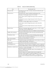
... and 76 of the error. Interface cable connection Check that the disk SCSI ID is set so that all disk drives. Drive selection address Check that the SCSI interface cable is correctly connected between pin 3 and 4 of the SCSI connector. If the AC voltage level is abnormal or there is a ...lot of electrical noise, notify the user of the SCSI connector. For NP model, check the voltage between the disk drive and controller. Electrical noise Make sure the maximum ripple peak-to 5.25V DC. See Section 5.3. Check the ...
... and 76 of the error. Interface cable connection Check that the disk SCSI ID is set so that all disk drives. Drive selection address Check that the SCSI interface cable is correctly connected between pin 3 and 4 of the SCSI connector. If the AC voltage level is abnormal or there is a ...lot of electrical noise, notify the user of the SCSI connector. For NP model, check the voltage between the disk drive and controller. Electrical noise Make sure the maximum ripple peak-to 5.25V DC. See Section 5.3. Check the ...

Product Manual
Page 119
... Recovery Methods" of a command, a command with the same tag number was issued. 4E 00 An overlap command was received. 4D xx Before completion of the SCSI Logical Interface Specifications. Sense key 00 3 4 1 3 E 5 4 or B B Table 7.1 Definition of sense data. For details of sense data, refer to allocate the alternate ..., such as an invalid operation code, occurred. 90 00 The RESERVE or RELEASE command cannot be executed because the SCSI ID of the initiator was not posted in the SELECTION phase. 44 xx A hardware error occurred inside the HDD. 47 xx A parity error occurred ...
... Recovery Methods" of a command, a command with the same tag number was issued. 4E 00 An overlap command was received. 4D xx Before completion of the SCSI Logical Interface Specifications. Sense key 00 3 4 1 3 E 5 4 or B B Table 7.1 Definition of sense data. For details of sense data, refer to allocate the alternate ..., such as an invalid operation code, occurred. 90 00 The RESERVE or RELEASE command cannot be executed because the SCSI ID of the initiator was not posted in the SELECTION phase. 44 xx A hardware error occurred inside the HDD. 47 xx A parity error occurred ...

Product Manual
Page 122
... factory shipment Note: See the description of Section 5.3 for details of 8-bit bus Force Single Ended Open Follows DIFFSNS signal level on NP model drives only) Setting item SCSI ID Write protect 1 - 2 Open Short Open Short Open Short Open Short Open Short Open Short Open Short Open Short Pin pair 3 - 4 5 - 6 7 - 8 9 - 10 Setting contents...
... factory shipment Note: See the description of Section 5.3 for details of 8-bit bus Force Single Ended Open Follows DIFFSNS signal level on NP model drives only) Setting item SCSI ID Write protect 1 - 2 Open Short Open Short Open Short Open Short Open Short Open Short Open Short Open Short Pin pair 3 - 4 5 - 6 7 - 8 9 - 10 Setting contents...

Product Manual
Page 128
...name given to a device which identifies an SCSI device on that status. Each SCSI device must have a unique ID. Target This is the SCSI device that was detected. Status This is completed, which corresponds to one bit of the data bus. The SCSI IDs can be 0 to the initiator by the ...initiator. 124 Downloaded from www.Manualslib.com manuals search engine C141-E270 It contains information for reporting detailed information on the SCSI bus. Sense Data When several items of information reported...
...name given to a device which identifies an SCSI device on that status. Each SCSI device must have a unique ID. Target This is the SCSI device that was detected. Status This is completed, which corresponds to one bit of the data bus. The SCSI IDs can be 0 to the initiator by the ...initiator. 124 Downloaded from www.Manualslib.com manuals search engine C141-E270 It contains information for reporting detailed information on the SCSI bus. Sense Data When several items of information reported...
Product Manual
Page 133
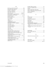
... type LVD 16-bit SCSI 120 SCA2 type SCSI connector 59 SCSI bus configuration 20 SCSI bus connection 74 SCSI cable connection 66 SCSI connector 120, 121 SCSI connector signal allocation............120, 121 SCSI function specification 29 SCSI ID setting 76, 77 SCSI interface error 116 SCSI standard 14 sector format ...service life 100 service system 101 setting bus width of SCSI interface 79 setting check list (NP model only 81 setting of SCSI interface operation mode.........79 setting parameter 89 setting SCSI terminator power supply 78 setting terminal 75, 117 setting terminal...
... type LVD 16-bit SCSI 120 SCA2 type SCSI connector 59 SCSI bus configuration 20 SCSI bus connection 74 SCSI cable connection 66 SCSI connector 120, 121 SCSI connector signal allocation............120, 121 SCSI function specification 29 SCSI ID setting 76, 77 SCSI interface error 116 SCSI standard 14 sector format ...service life 100 service system 101 setting bus width of SCSI interface 79 setting check list (NP model only 81 setting of SCSI interface operation mode.........79 setting parameter 89 setting SCSI terminator power supply 78 setting terminal 75, 117 setting terminal...

