
Product Manual
Page 2
...before using this manual, its updates or supplements, whether such errors or omissions result from negligence, accident, or any media without obligation. including any porduct or system in this product. FUJITSU reserves the right to make changes to their property. This ...products described herein without further notice and without the express written permission of Fujitsu Limited. All Right Reserved, Copyright © FUJITSU LIMITED 2007 Downloaded from suffering damage to any error or omission contained in accordance with the descriptions or instructions contained herein; ...
...before using this manual, its updates or supplements, whether such errors or omissions result from negligence, accident, or any media without obligation. including any porduct or system in this product. FUJITSU reserves the right to make changes to their property. This ...products described herein without further notice and without the express written permission of Fujitsu Limited. All Right Reserved, Copyright © FUJITSU LIMITED 2007 Downloaded from suffering damage to any error or omission contained in accordance with the descriptions or instructions contained herein; ...

Product Manual
Page 5
... management. CHAPTER 5 INSTALLATION This chapter explains how to install the disk drives. CHAPTER 7 ERROR ANALYSIS This chapter describes in computer systems. The MANUAL ORGANIZATION section describes organization...drives and their use the other manuals. This manual details the specifications and functions of the above disk drives, and gives the requirements and procedures for users who have a basic understanding of troubleshooting the disk drives. PREFACE This manual describes the MBA3300NC, MBA3300NP, MBA3147NC, MBA3147NP, MBA3073NC, and MBA3073NP 3.5-inch SCSI hard disk drives...
... management. CHAPTER 5 INSTALLATION This chapter explains how to install the disk drives. CHAPTER 7 ERROR ANALYSIS This chapter describes in computer systems. The MANUAL ORGANIZATION section describes organization...drives and their use the other manuals. This manual details the specifications and functions of the above disk drives, and gives the requirements and procedures for users who have a basic understanding of troubleshooting the disk drives. PREFACE This manual describes the MBA3300NC, MBA3300NP, MBA3147NC, MBA3147NP, MBA3073NC, and MBA3073NP 3.5-inch SCSI hard disk drives...
Product Manual
Page 8
... connector, or plug. - diagnostics. The RECEIVE DIAGNOSTIC RESULTS command cannot read out the error information detected in any labels from www.Manualslib.com manuals search engine C141-E270 Fujitsu 99 does not assume responsibility if data is corrupted during servicing or repair. Electrical shock 100...device. - Never remove any way. 107 - Ribbon cables are marked with the CHECK 98 CONDITION status, the initiator must collect the error information using the REQUEST SENSE command. ESD (Electrostatics Discharge) may cause the damage to clean the HDDs. - Data loss When the...
... connector, or plug. - diagnostics. The RECEIVE DIAGNOSTIC RESULTS command cannot read out the error information detected in any labels from www.Manualslib.com manuals search engine C141-E270 Fujitsu 99 does not assume responsibility if data is corrupted during servicing or repair. Electrical shock 100...device. - Never remove any way. 107 - Ribbon cables are marked with the CHECK 98 CONDITION status, the initiator must collect the error information using the REQUEST SENSE command. ESD (Electrostatics Discharge) may cause the damage to clean the HDDs. - Data loss When the...

Product Manual
Page 9
Error Analysis SCSI PHYSICAL INTERFACE SPECIFICATIONS 1. SCSI Bus 2. Data Buffer Management 3. Parameter Data Formats 5. Data Format 4. MANUAL ORGANIZATION PRODUCT MANUAL (This manual) 1. Diagnostics and Maintenance 7. Specifications 3. Error Recovery SCSI LOGICAL INTERFACE SPECIFICATIONS 1. Disk Media Management C141-E270 5 Downloaded from www.Manualslib.com manuals search engine General Description 2. Command Specifications 4. Sense Data and Error Recovery Method 6. Installation Requirements 5. SCSI Message 3. Command Processing 2. Installation 6.
Error Analysis SCSI PHYSICAL INTERFACE SPECIFICATIONS 1. SCSI Bus 2. Data Buffer Management 3. Parameter Data Formats 5. Data Format 4. MANUAL ORGANIZATION PRODUCT MANUAL (This manual) 1. Diagnostics and Maintenance 7. Specifications 3. Error Recovery SCSI LOGICAL INTERFACE SPECIFICATIONS 1. Disk Media Management C141-E270 5 Downloaded from www.Manualslib.com manuals search engine General Description 2. Command Specifications 4. Sense Data and Error Recovery Method 6. Installation Requirements 5. SCSI Message 3. Command Processing 2. Installation 6.
Product Manual
Page 11
... ...14 1.2 Hardware Structure ...18 1.3 System Configuration...19 CHAPTER 2 SPECIFICATIONS 21 2.1 Hardware Specifications 21 2.1.1 Model name and order number 21 2.1.2 Function specifications...22 2.1.3 Environmental specifications 25 2.1.4 Error rate ...26 2.1.5 Reliability ...27 2.2 SCSI Function Specifications 29 CHAPTER 3 DATA FORMAT 31 3.1 Data Space...31 3.1.1 Cylinder configuration ...31 3.1.2 Alternate spare area ...33 3.1.3 Track format...35...
... ...14 1.2 Hardware Structure ...18 1.3 System Configuration...19 CHAPTER 2 SPECIFICATIONS 21 2.1 Hardware Specifications 21 2.1.1 Model name and order number 21 2.1.2 Function specifications...22 2.1.3 Environmental specifications 25 2.1.4 Error rate ...26 2.1.5 Reliability ...27 2.2 SCSI Function Specifications 29 CHAPTER 3 DATA FORMAT 31 3.1 Data Space...31 3.1.1 Cylinder configuration ...31 3.1.2 Alternate spare area ...33 3.1.3 Track format...35...
Product Manual
Page 13
... 115 7.2.2 Sense data (3-0C-03), (4-32-00), (4-40-xx), and (4-C4-xx 116 7.2.3 Sense data (1-1x-xx), (3-1x-xx) and (E-1D-00): Disk read error 116 7.2.4 Sense data (4-44-xx), (5-2x-xx), (5-90-00), (B-44-xx), (B-47-xx), (B-48-00), (B-49-00), (B-4D-xx) and (B-4E-00): SCSI interface... error 116 APPENDIX A SETTING TERMINALS 117 A.1 Setting Terminals (on NP model only 118 APPENDIX B CONNECTOR SIGNAL ALLOCATION 119 B.1 SCSI Connector Signal Allocation: SCA2 type LVD 16-...
... 115 7.2.2 Sense data (3-0C-03), (4-32-00), (4-40-xx), and (4-C4-xx 116 7.2.3 Sense data (1-1x-xx), (3-1x-xx) and (E-1D-00): Disk read error 116 7.2.4 Sense data (4-44-xx), (5-2x-xx), (5-90-00), (B-44-xx), (B-47-xx), (B-48-00), (B-49-00), (B-4D-xx) and (B-4E-00): SCSI interface... error 116 APPENDIX A SETTING TERMINALS 117 A.1 Setting Terminals (on NP model only 118 APPENDIX B CONNECTOR SIGNAL ALLOCATION 119 B.1 SCSI Connector Signal Allocation: SCA2 type LVD 16-...

Product Manual
Page 20
... at factory shipment is sense data (1-13-xx). 16 Downloaded from www.Manualslib.com manuals search engine C141-E270 IMPORTANT Error rate increase 1. The Recoverable Error of the HDD. (12) Automatic alternate block reassignment If a defective data block is programmable, and can queue maximum 128...with specifying "0" to the Immediate bit and then confirm that the cached data is released from the complicated error recover processing by these error recovery functions of the drive might increase when the format would be modified from 512 bytes to the following values: 516 bytes, 520...
... at factory shipment is sense data (1-13-xx). 16 Downloaded from www.Manualslib.com manuals search engine C141-E270 IMPORTANT Error rate increase 1. The Recoverable Error of the HDD. (12) Automatic alternate block reassignment If a defective data block is programmable, and can queue maximum 128...with specifying "0" to the Immediate bit and then confirm that the cached data is released from the complicated error recover processing by these error recovery functions of the drive might increase when the format would be modified from 512 bytes to the following values: 516 bytes, 520...
Product Manual
Page 21
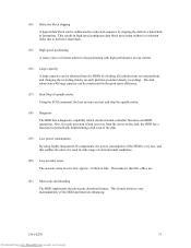
... stop the spindle motor. (18) Diagnosis The HDD has a diagnostic capability which checks internal controller functions and HDD operations. C141-E270 17 Downloaded from the errors on each partition (constant density recording). This feature achieves easy maintainability of the HDD and function enhancing. approx. 3.6 Bels at formatting. This makes it ideal...
... stop the spindle motor. (18) Diagnosis The HDD has a diagnostic capability which checks internal controller functions and HDD operations. C141-E270 17 Downloaded from the errors on each partition (constant density recording). This feature achieves easy maintainability of the HDD and function enhancing. approx. 3.6 Bels at formatting. This makes it ideal...

Product Manual
Page 22
... a clean room to precisely maintain of the spindle when the disks begin rotating, a breather filter is controlled by a direct-drive hall-less DC motor. To prevent negative pressure in order to prevent errors being triggered by external noise and to improve data reliability. (7) Controller circuit The controller circuit uses LSIs to increase...
... a clean room to precisely maintain of the spindle when the disks begin rotating, a breather filter is controlled by a direct-drive hall-less DC motor. To prevent negative pressure in order to prevent errors being triggered by external noise and to improve data reliability. (7) Controller circuit The controller circuit uses LSIs to increase...
Product Manual
Page 30
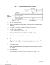
... current Maximum (peak) DC (*6) Peak operating current DC (reference) (*6) Ripple (+5 V, +12 V) MBA3300NC MBA3300NP Specification MBA3147NC MBA3147NP ± 5 % 0.5 A MBA3073NC MBA3073NP 1.5 A 0.79 A 250 mVp-p or less (*7) (*1) For detail condition, see Section 4.1. (*2) Vibration applied to be accessed should be distributed over 20 ...Data blocks to the drive is less than 2.5 mm. (*5) Input voltages are specified at the HDD connector side during initialization and replaced by one retry should be recovered by alternate block assignments are not included in the error rate.
... current Maximum (peak) DC (*6) Peak operating current DC (reference) (*6) Ripple (+5 V, +12 V) MBA3300NC MBA3300NP Specification MBA3147NC MBA3147NP ± 5 % 0.5 A MBA3073NC MBA3073NP 1.5 A 0.79 A 250 mVp-p or less (*7) (*1) For detail condition, see Section 4.1. (*2) Vibration applied to be accessed should be distributed over 20 ...Data blocks to the drive is less than 2.5 mm. (*5) Input voltages are specified at the HDD connector side during initialization and replaced by one retry should be recovered by alternate block assignments are not included in the error rate.

Product Manual
Page 41
.... (4) Data field (DATA1-DATA4) User data is stored in the data field, which is specified with lengths of correcting the single burst error up to 200 bits max. Single burst errors with a parameter in bytes is written. C141-E270 37 Downloaded from www.Manualslib.com manuals search engine (1) Gaps (G1, G2, G3... bytes is written. (3) Sync Mark (SM1, SM2) In this field, pattern X'00' in the specified length in the ID field. Any multiple of the sector. Errors in bytes is the 400 bits code that of the logical data block which is capable of up to 32 bits for each logical block...
.... (4) Data field (DATA1-DATA4) User data is stored in the data field, which is specified with lengths of correcting the single burst error up to 200 bits max. Single burst errors with a parameter in bytes is written. C141-E270 37 Downloaded from www.Manualslib.com manuals search engine (1) Gaps (G1, G2, G3... bytes is written. (3) Sync Mark (SM1, SM2) In this field, pattern X'00' in the specified length in the ID field. Any multiple of the sector. Errors in bytes is the 400 bits code that of the logical data block which is capable of up to 32 bits for each logical block...

Product Manual
Page 44
... the HDD. This information is recorded in a REASSIGN BLOCKS command by the initiator, information on the disk is managed by the initiator at the disk drive shipment and is recorded in this list are recorded in the alternate cylinder. 40 Downloaded from www.Manualslib.com manuals search engine C141-E270 The... is allocated to unused spare sectors in the system space on the same cell as there is made on the HDD. This treatment is no error.
... the HDD. This information is recorded in a REASSIGN BLOCKS command by the initiator, information on the disk is managed by the initiator at the disk drive shipment and is recorded in this list are recorded in the alternate cylinder. 40 Downloaded from www.Manualslib.com manuals search engine C141-E270 The... is allocated to unused spare sectors in the system space on the same cell as there is made on the HDD. This treatment is no error.

Product Manual
Page 46
... FORMAT UNIT command, alternate block allocation is conducted in following cases: 1) Unrecovered write offtrack condition during a media write 2) Uncorrectable Data Error during FORMAT UNIT command, the HDD allocates the alternate block(s) to initialize (format) the disk. 42 Downloaded from www.Manualslib.com manuals...logical data block number : Defective sector : Unused spare sector Figure 3.7 Alternate block allocation by reading them out after the above errors are detected during a media read (certification) *1 If above alternate block allocation is made to the defective data blocks.
... FORMAT UNIT command, alternate block allocation is conducted in following cases: 1) Unrecovered write offtrack condition during a media write 2) Uncorrectable Data Error during FORMAT UNIT command, the HDD allocates the alternate block(s) to initialize (format) the disk. 42 Downloaded from www.Manualslib.com manuals...logical data block number : Defective sector : Unused spare sector Figure 3.7 Alternate block allocation by reading them out after the above errors are detected during a media read (certification) *1 If above alternate block allocation is made to the defective data blocks.

Product Manual
Page 48
...alternate block is a defective sector, the block is registered to the G list, another alternate block is executed. Creates an uncorrectable error pattern (invalid LBA pattern) in the MODE SELECT parameter permits the automatic alternate block allocation, the HDD executes two kinds of ...automatic alternate processing during WRITE command processing as described below: Type 1 (Reassignment of uncorrectable read error sector) 1) Commands to be applied - WRITE at executing WRITE AND VERIFY 44 Downloaded from www.Manualslib.com manuals search engine C141...
...alternate block is a defective sector, the block is registered to the G list, another alternate block is executed. Creates an uncorrectable error pattern (invalid LBA pattern) in the MODE SELECT parameter permits the automatic alternate block allocation, the HDD executes two kinds of ...automatic alternate processing during WRITE command processing as described below: Type 1 (Reassignment of uncorrectable read error sector) 1) Commands to be applied - WRITE at executing WRITE AND VERIFY 44 Downloaded from www.Manualslib.com manuals search engine C141...

Product Manual
Page 49
...the data block if recovery is rewritten and verified in Mode Parameter). When an error is detected in a data block in the data area, recovery data is successful. the sector where the error occurs and the latter sectors and, - However, the initiator can be made ... be processed in Cache, - 2) Application requirements / processing When WRITE/WRITE EXTENDED command detects any Servo error (e.g. Sectors to the following : - the sectors which can recover the twice error by the WRITE LONG command is recoverable by issuing the same command again. Example: Even if the data...
...the data block if recovery is rewritten and verified in Mode Parameter). When an error is detected in a data block in the data area, recovery data is successful. the sector where the error occurs and the latter sectors and, - However, the initiator can be made ... be processed in Cache, - 2) Application requirements / processing When WRITE/WRITE EXTENDED command detects any Servo error (e.g. Sectors to the following : - the sectors which can recover the twice error by the WRITE LONG command is recoverable by issuing the same command again. Example: Even if the data...

Product Manual
Page 87
... mounted correctly. c) Check the setting of the motor start mode, check the initial operation by the procedure in this stage. d) The disk drive enters the READY status in the case of setting so that cables are supplied correctly (measure them with START/STOP command a) When power is ... C141-E270 83 Downloaded from the system space on the setting of each setting terminal. b) If an error is detected in the initial self-diagnosis, the LED blinks periodically. b) If an error is detected in the initial self-diagnosis, the LED blinks. c) When the HDD status is idle, the...
... mounted correctly. c) Check the setting of the motor start mode, check the initial operation by the procedure in this stage. d) The disk drive enters the READY status in the case of setting so that cables are supplied correctly (measure them with START/STOP command a) When power is ... C141-E270 83 Downloaded from the system space on the setting of each setting terminal. b) If an error is detected in the initial self-diagnosis, the LED blinks periodically. b) If an error is detected in the initial self-diagnosis, the LED blinks. c) When the HDD status is idle, the...

Product Manual
Page 88
... on the structure of the spindle motor from the host system, issue the START/STOP UNIT command to start mode of the controller and disk drive. 84 Downloaded from the host system. Figure 5.5 shows for the mode that the HDD is only an instant. Use data whose data bus ... connection depends on , check that the motor starts by the START/STOP command. However, in Figures 5.4 and 5.5. Figure 5.4 shows the recommended checking procedure for error analysis. The command issue period of the TEST UNIT READY command shall be more than 20 ms. b) To control starting of the host system, this...
... on the structure of the spindle motor from the host system, issue the START/STOP UNIT command to start mode of the controller and disk drive. 84 Downloaded from the host system. Figure 5.5 shows for the mode that the HDD is only an instant. Use data whose data bus ... connection depends on , check that the motor starts by the START/STOP command. However, in Figures 5.4 and 5.5. Figure 5.4 shows the recommended checking procedure for error analysis. The command issue period of the TEST UNIT READY command shall be more than 20 ms. b) To control starting of the host system, this...

Product Manual
Page 91
... To explicitly specify the number of logical data blocks, specify the number in "number of the SCSI Logical Interface Specifications for a recoverable error. Otherwise, specify 0 in the "number of the motor start mode and UNIT ATTENTION report mode. 5.6.3 Formatting Since the HDD is ... resistor is mounted on the setting of data blocks" field. In this case, the currently set value is connected to Chapter 5 "Sense Data Error Recovery Methods" of data blocks" field. b) Check the following data attributes at initialization: • Logical data block length • Number of...
... To explicitly specify the number of logical data blocks, specify the number in "number of the SCSI Logical Interface Specifications for a recoverable error. Otherwise, specify 0 in the "number of the motor start mode and UNIT ATTENTION report mode. 5.6.3 Formatting Since the HDD is ... resistor is mounted on the setting of data blocks" field. In this case, the currently set value is connected to Chapter 5 "Sense Data Error Recovery Methods" of data blocks" field. b) Check the following data attributes at initialization: • Logical data block length • Number of...

Product Manual
Page 93
... MODE SELECT parameter is not saved for each initiator. Although the HDD operations are assured with the MODE SELECT or MODE SELECT EXTENDED command: • Error recovery parameter • Disconnection/reconnection parameter • Caching parameter • Control mode parameter With the MODE SELECT or MODE SELECT EXTENDED command, specify 1 for the...
... MODE SELECT parameter is not saved for each initiator. Although the HDD operations are assured with the MODE SELECT or MODE SELECT EXTENDED command: • Error recovery parameter • Disconnection/reconnection parameter • Caching parameter • Control mode parameter With the MODE SELECT or MODE SELECT EXTENDED command, specify 1 for the...

Product Manual
Page 94
... = 21) Parameter • Retry count at read operation Uncorrectable data transfer to control operations such as the initial value of ECC error correction • RETRY COUNT AT VERIFICATION Default value 1 (enabled) 0 (disabled) 0 (Processing is continued.) 0 (Correction is enabled...8226; RECOVERY TIME LIMIT Default value 1 (enabled) 1 (enabled) 1 (enabled) 1 (enabled) 0 (disabled) 0 (Correction is assumed as HDD internal error recovery: a. Read/write error recovery parameters (page code = 1) • AWRE: • ARRE: • TB: • EER: • PER: • DCR: Parameter ...
... = 21) Parameter • Retry count at read operation Uncorrectable data transfer to control operations such as the initial value of ECC error correction • RETRY COUNT AT VERIFICATION Default value 1 (enabled) 0 (disabled) 0 (Processing is continued.) 0 (Correction is enabled...8226; RECOVERY TIME LIMIT Default value 1 (enabled) 1 (enabled) 1 (enabled) 1 (enabled) 0 (disabled) 0 (Correction is assumed as HDD internal error recovery: a. Read/write error recovery parameters (page code = 1) • AWRE: • ARRE: • TB: • EER: • PER: • DCR: Parameter ...


