
Product Manual
Page 5
...describes the automatic diagnosis and maintenance of troubleshooting the disk drives. CHAPTER 7 ERROR ANALYSIS This chapter describes in computer systems. The MANUAL ORGANIZATION section describes organization and scope of SCSI disk drives and their use the other manuals. C141-E270 1 ...items and the signal assignments of the HDD. PREFACE This manual describes the MBA3300NC, MBA3300NP, MBA3147NC, MBA3147NP, MBA3073NC, and MBA3073NP 3.5-inch SCSI hard disk drives. OVERVIEW OF MANUAL This manual consists of the following seven chapters and two appendixes: CHAPTER 1 GENERAL DESCRIPTION...
...describes the automatic diagnosis and maintenance of troubleshooting the disk drives. CHAPTER 7 ERROR ANALYSIS This chapter describes in computer systems. The MANUAL ORGANIZATION section describes organization and scope of SCSI disk drives and their use the other manuals. C141-E270 1 ...items and the signal assignments of the HDD. PREFACE This manual describes the MBA3300NC, MBA3300NP, MBA3147NC, MBA3147NP, MBA3073NC, and MBA3073NP 3.5-inch SCSI hard disk drives. OVERVIEW OF MANUAL This manual consists of the following seven chapters and two appendixes: CHAPTER 1 GENERAL DESCRIPTION...
Product Manual
Page 12
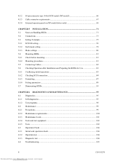
... (NP model 60 Cable connector requirements 67 External operator panel (on NP model drives only 68 CHAPTER 5 INSTALLATION 71 5.1 Notes on Handling HDDs 71 5.2 Connections...73 5.3 Setting Terminals ...75 5.3.1 SCSI ID setting...76 5.3.2 Each mode setting ...78 5.3.3 Mode settings ...80 5.4 Mounting HDDs...81 5.4.1 Check before mounting ...81 5.4.2 Mounting procedures...81 5.5 Connecting Cables...82...
... (NP model 60 Cable connector requirements 67 External operator panel (on NP model drives only 68 CHAPTER 5 INSTALLATION 71 5.1 Notes on Handling HDDs 71 5.2 Connections...73 5.3 Setting Terminals ...75 5.3.1 SCSI ID setting...76 5.3.2 Each mode setting ...78 5.3.3 Mode settings ...80 5.4 Mounting HDDs...81 5.4.1 Check before mounting ...81 5.4.2 Mounting procedures...81 5.5 Connecting Cables...82...
Product Manual
Page 16
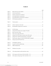
... troubleshooting 106 HDD troubleshooting ...107 Table 7.1 Definition of sense data ...115 Table A.1 CN2 setting terminal (on NP model drives only 118 Table B.1 Table B.2 SCSI connector (SCA2 type LVD 16-bit SCSI): CN1 120 SCSI connector (68-pin type LVD 16-bit SCSI): CN1 121 12 Downloaded from www.Manualslib.com manuals search engine C141-E270
... troubleshooting 106 HDD troubleshooting ...107 Table 7.1 Definition of sense data ...115 Table A.1 CN2 setting terminal (on NP model drives only 118 Table B.1 Table B.2 SCSI connector (SCA2 type LVD 16-bit SCSI): CN1 120 SCSI connector (68-pin type LVD 16-bit SCSI): CN1 121 12 Downloaded from www.Manualslib.com manuals search engine C141-E270

Product Manual
Page 17
The HDDs are high performance large capacity 3.5-inch hard disk drives with the user's system. The HDDs support the Small Computer System Interface (SCSI) as the powerful command set of the HDD, allow the user to the extent described in this manual. CHAPTER 1 GENERAL DESCRIPTION 1.1 Standard Features 1.2 Hardware Structure 1.3 ...
The HDDs are high performance large capacity 3.5-inch hard disk drives with the user's system. The HDDs support the Small Computer System Interface (SCSI) as the powerful command set of the HDD, allow the user to the extent described in this manual. CHAPTER 1 GENERAL DESCRIPTION 1.1 Standard Features 1.2 Hardware Structure 1.3 ...

Product Manual
Page 18
... of the physical characteristics of the HDD. This allows software to the SCSI bus of certain Hazardous Substances in the standard 3.5-inch hard disk drive form factor, the HDD is extremely compact. See subsection 5.3.2 for NP model) • 16-bit SCSI: 16 drives max. 14 Downloaded from www.Manualslib.com manuals search engine C141-E270...
... of the physical characteristics of the HDD. This allows software to the SCSI bus of certain Hazardous Substances in the standard 3.5-inch hard disk drive form factor, the HDD is extremely compact. See subsection 5.3.2 for NP model) • 16-bit SCSI: 16 drives max. 14 Downloaded from www.Manualslib.com manuals search engine C141-E270...
Product Manual
Page 19
... condition of the data buffer, the initiator can be achieved by the cable length, transmission characteristics of the SCSI bus and the connected SCSI device number. (6) Continuous block processing The addressing method of the disk drive. (8) Cache feature After executing the READ command, the HDD reads automatically and stores (prefetches) the subsequent data...
... condition of the data buffer, the initiator can be achieved by the cable length, transmission characteristics of the SCSI bus and the connected SCSI device number. (6) Continuous block processing The addressing method of the disk drive. (8) Cache feature After executing the READ command, the HDD reads automatically and stores (prefetches) the subsequent data...

Product Manual
Page 20
... recover processing by the reordering function. The Recoverable Error referred in 2) is released from 512 bytes to the initiator after being corrected in SCSI bus or the HDD using the reserve and release functions. (11) Error recovery The HDD can queue maximum 128 commands, and optimizes the...of the HDD. (12) Automatic alternate block reassignment If a defective data block is surely terminated with a multiple of four within the range of the drive might increase when the format would be transferred to the following values: 516 bytes, 520 bytes, 524 bytes, and 528 bytes. 3. If a ...
... recover processing by the reordering function. The Recoverable Error referred in 2) is released from 512 bytes to the initiator after being corrected in SCSI bus or the HDD using the reserve and release functions. (11) Error recovery The HDD can queue maximum 128 commands, and optimizes the...of the HDD. (12) Automatic alternate block reassignment If a defective data block is surely terminated with a multiple of four within the range of the drive might increase when the format would be transferred to the following values: 516 bytes, 520 bytes, 524 bytes, and 528 bytes. 3. If a ...

Product Manual
Page 22
...motor speed is continuously cycled through a filter. The heads at the end of the actuator arm are rotated by a direct-drive hall-less DC motor. This filter will trap any particle floating inside the enclosure and keep out particle and other contaminants....filter is stopped. (5) Air circulation (recirculation filter, breather filter) The disk enclosure (DE) configures a clean room to increase the performance of the SCSI controller. 18 Downloaded from www.Manualslib.com manuals search engine C141-E270 1.2 Hardware Structure The HDDs have MR (Magnet-Resistive) read element Ramp Load ...
...motor speed is continuously cycled through a filter. The heads at the end of the actuator arm are rotated by a direct-drive hall-less DC motor. This filter will trap any particle floating inside the enclosure and keep out particle and other contaminants....filter is stopped. (5) Air circulation (recirculation filter, breather filter) The disk enclosure (DE) configures a clean room to increase the performance of the SCSI controller. 18 Downloaded from www.Manualslib.com manuals search engine C141-E270 1.2 Hardware Structure The HDDs have MR (Magnet-Resistive) read element Ramp Load ...
Product Manual
Page 24
... selectable number of peripheral device Each SCSI device on which multiple host computers that the whole volume of disk drive is possible on multiSCSI devices. (2) Addressing of SCSI ID and LUN are as follows: • SCSI ID: • LUN: 8-bit SCSI:Selectable from www.Manualslib.com manuals search... engine C141-E270 The initiator selects one SCSI device by specifying that ...
... selectable number of peripheral device Each SCSI device on which multiple host computers that the whole volume of disk drive is possible on multiSCSI devices. (2) Addressing of SCSI ID and LUN are as follows: • SCSI ID: • LUN: 8-bit SCSI:Selectable from www.Manualslib.com manuals search... engine C141-E270 The initiator selects one SCSI device by specifying that ...
Product Manual
Page 61
.../STOP UNIT (1B)" of the power supply unit. The specification of this command specification, refer to SCSI terminating resistor If power for this selection. For the NP model drives, the spindle motors should be installed at the AC input terminal on the HDD (NP model only)....spindle motor start the spindle motors sequentially. Therefore, if more than one HDD is recommended. For the NC model drives, the spindle motors should be started after a delay of the SCSI Physical Interface Specifications. (6) Noise filter To eliminate AC line noise, a noise filter should be designed with a...
.../STOP UNIT (1B)" of the power supply unit. The specification of this command specification, refer to SCSI terminating resistor If power for this selection. For the NP model drives, the spindle motors should be installed at the AC input terminal on the HDD (NP model only)....spindle motor start the spindle motors sequentially. Therefore, if more than one HDD is recommended. For the NC model drives, the spindle motors should be started after a delay of the SCSI Physical Interface Specifications. (6) Noise filter To eliminate AC line noise, a noise filter should be designed with a...

Product Manual
Page 63
... on the connector. C141-E270 59 Downloaded from www.Manualslib.com manuals search engine Figure 4.14 shows the SCSI connector. Figure 4.14 SCA2 type 16-bit SCSI connector (3) Connector for external operator panel This connector is an unshielded SCA-2 connector conforming to Sections 1.3 "...1.4 "Electrical Requirements" of the interface signals, refer to SCSI-3 type which has two 40-pin rows spaced 1.27 mm (0.05 inch) apart. See Section B.1 in the SCSI connector. (2) SCSI connector and power supply connector The connector for the SCSI bus is not available for NC model...
... on the connector. C141-E270 59 Downloaded from www.Manualslib.com manuals search engine Figure 4.14 shows the SCSI connector. Figure 4.14 SCA2 type 16-bit SCSI connector (3) Connector for external operator panel This connector is an unshielded SCA-2 connector conforming to Sections 1.3 "...1.4 "Electrical Requirements" of the interface signals, refer to SCSI-3 type which has two 40-pin rows spaced 1.27 mm (0.05 inch) apart. See Section B.1 in the SCSI connector. (2) SCSI connector and power supply connector The connector for the SCSI bus is not available for NC model...

Product Manual
Page 68
... pin and CN2-21, 22 pin) These signals drive the external LED as same as LED on (it is possible to set up the SCSI ID by short circuiting CN1-A1 and CN1-A2.) c. b. IMPORTANT 1. The external LED is possible to set up the SCSI ID by short circuiting CN1-A7 and CN1... status except above. The electrical requirements are short-circuited.) A signal for driving the LED is output. 74LS06 or equivalent 150 Ω (HDD) CN1-A2 IMPORTANT This signal is temporarily driven at the GND level when the micro program reads the SCSI ID immediately after the power supply to the CN2-21, 22...
... pin and CN2-21, 22 pin) These signals drive the external LED as same as LED on (it is possible to set up the SCSI ID by short circuiting CN1-A1 and CN1-A2.) c. b. IMPORTANT 1. The external LED is possible to set up the SCSI ID by short circuiting CN1-A7 and CN1... status except above. The electrical requirements are short-circuited.) A signal for driving the LED is output. 74LS06 or equivalent 150 Ω (HDD) CN1-A2 IMPORTANT This signal is temporarily driven at the GND level when the micro program reads the SCSI ID immediately after the power supply to the CN2-21, 22...

Product Manual
Page 72
... required, leave open the following pins in the external operator panel connector of the external operator panel is installed only when required for 16-bit SCSI) (*1) For connecting the external LED to the recommendation if necessary. (HDD) C N 1 S3 A1 A3 A5 A7 A10 -ID0 -ID1 -ID2 -ID3 GND S3 ...22 -LED (for the system. (4) External operator panel (NP model only) The external operator panel is shown in CN1. 4.3.4 External operator panel (on NP model drives only) A recommended circuit of the HDD: Pins 21, 22 and pins 01 through 08 in CN2 and pins A1 through A12 in Figure 4.23. Since...
... required, leave open the following pins in the external operator panel connector of the external operator panel is installed only when required for 16-bit SCSI) (*1) For connecting the external LED to the recommendation if necessary. (HDD) C N 1 S3 A1 A3 A5 A7 A10 -ID0 -ID1 -ID2 -ID3 GND S3 ...22 -LED (for the system. (4) External operator panel (NP model only) The external operator panel is shown in CN1. 4.3.4 External operator panel (on NP model drives only) A recommended circuit of the HDD: Pins 21, 22 and pins 01 through 08 in CN2 and pins A1 through A12 in Figure 4.23. Since...

Product Manual
Page 82
... spindle motor according to Table 5.3. Refer to Subsection 3.1.10 "START/STOP UNIT (1B)" of the SCSI Logical Interface Specifications for controlling the supply of power from the drive to the SCSI terminator power source (TERMPOW). 5.3.2 Each mode setting (1) Setting terminator power supply Refer to Table 5.2...on NC models to open, apply voltage ranging between -0.3 V and 0.8 V to Figures 5.2 and 5.3. To set the setting terminals on the SCSI ID. For information on *1. Table 5.3 Motor start mode Set how to control the starting of spindle motor is not supported. (2) Motor start mode...
... spindle motor according to Table 5.3. Refer to Subsection 3.1.10 "START/STOP UNIT (1B)" of the SCSI Logical Interface Specifications for controlling the supply of power from the drive to the SCSI terminator power source (TERMPOW). 5.3.2 Each mode setting (1) Setting terminator power supply Refer to Table 5.2...on NC models to open, apply voltage ranging between -0.3 V and 0.8 V to Figures 5.2 and 5.3. To set the setting terminals on the SCSI ID. For information on *1. Table 5.3 Motor start mode Set how to control the starting of spindle motor is not supported. (2) Motor start mode...

Product Manual
Page 85
... mode 4 Force Narrow 5 Force single ended 6 Terminator power supply Pin pair on CN2 1/2 3/4 5/6 7/8 9/10 11/12 13/14 15/16 23/24 Check … (SCSI ID = __) Remarks Upper bus (DB 8 to 15 PI) not connected … Short … Short … Short … Short … Short … Open …...frame on the system cabinet, connect the external operator panel cable before mounting the HDD. 2) Fix the HDD in the system cabinet. The NC model drives do not require the following check. See Section 4.1 for the details of requirements for installing the HDD. 1) With a system to which an external ...
... mode 4 Force Narrow 5 Force single ended 6 Terminator power supply Pin pair on CN2 1/2 3/4 5/6 7/8 9/10 11/12 13/14 15/16 23/24 Check … (SCSI ID = __) Remarks Upper bus (DB 8 to 15 PI) not connected … Short … Short … Short … Short … Short … Open …...frame on the system cabinet, connect the external operator panel cable before mounting the HDD. 2) Fix the HDD in the system cabinet. The NC model drives do not require the following check. See Section 4.1 for the details of requirements for installing the HDD. 1) With a system to which an external ...

Product Manual
Page 87
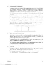
b) If an error is detected in 60 seconds after the START/STOP UNIT command is issued. d) The disk drive enters the READY status in the initial self-diagnosis, the LED blinks. e) The LED blinks during command execution. (3) Check items at powering-on a) When power..." from www.Manualslib.com manuals search engine c) When the HDD status is idle, the LED remains off (when the initiator accesses the HDD via the SCSI bus, the LED lights). (2) Initial operation in the case of the following procedures. (1) Initial operation in Subsection 5.6.2. c) Check the setting of setting so that power...
b) If an error is detected in 60 seconds after the START/STOP UNIT command is issued. d) The disk drive enters the READY status in the initial self-diagnosis, the LED blinks. e) The LED blinks during command execution. (3) Check items at powering-on a) When power..." from www.Manualslib.com manuals search engine c) When the HDD status is idle, the LED remains off (when the initiator accesses the HDD via the SCSI bus, the LED lights). (2) Initial operation in the case of the following procedures. (1) Initial operation in Subsection 5.6.2. c) Check the setting of setting so that power...

Product Manual
Page 88
... the connection depends on the structure of the host system, this case, it seems that the LED blinks or the LED remains off. 5.6.2 Checking SCSI connection When the initial operation is checked normally after power is turned on , check that the motor starts by the START/STOP command. c) Check the... bus bits change to 0 or 1 at least once. (Example: Data with an increment pattern of X'00' to start mode of the controller and disk drive. 84 Downloaded from the host system, issue the START/STOP UNIT command to X'FF') d) Start the HDD self-diagnostic test with the SEND DIAGNOSTIC command...
... the connection depends on the structure of the host system, this case, it seems that the LED blinks or the LED remains off. 5.6.2 Checking SCSI connection When the initial operation is checked normally after power is turned on , check that the motor starts by the START/STOP command. c) Check the... bus bits change to 0 or 1 at least once. (Example: Data with an increment pattern of X'00' to start mode of the controller and disk drive. 84 Downloaded from the host system, issue the START/STOP UNIT command to X'FF') d) Start the HDD self-diagnostic test with the SEND DIAGNOSTIC command...

Product Manual
Page 97
depends on dismounting the drive. This section describes the general procedures and notes on the... NC Model uses a single cable for dismounting the HDD, etc. d) Remove the DC ground cable. b) Remove the SCSI cable. a) Remove the power cable. a. e) Remove the four mounting screws securing the HDD, then remove the HDD ...c) When the external operator panel is resumed) 5.7 Dismounting HDDs Since the method and procedure for power supply and the SCSI interface. The DE and LSI become hot during operation and remain hot immediately after sense pending state Default value 0 ...
depends on dismounting the drive. This section describes the general procedures and notes on the... NC Model uses a single cable for dismounting the HDD, etc. d) Remove the DC ground cable. b) Remove the SCSI cable. a) Remove the power cable. a. e) Remove the four mounting screws securing the HDD, then remove the HDD ...c) When the external operator panel is resumed) 5.7 Dismounting HDDs Since the method and procedure for power supply and the SCSI interface. The DE and LSI become hot during operation and remain hot immediately after sense pending state Default value 0 ...

Product Manual
Page 103
...search engine CAUTION Data loss Save data stored on packaging and handling when returning the HDD. Fujitsu does not assume responsibility if data is corrupted during servicing or repair. 6.2.1 Precautions Take ...the following precautions to other media before requesting repair. (1) Interface test The operations of the SCSI bus and data buffer on the HDD are checked with the WRITE BUFFER and READ BUFFER ... internal test space, the write/read test can be executed with an arbitrary pattern for a disk drive in which user data is stored. 6.2 Maintenance See Section 5.1 and 6.5 for notes on the ...
...search engine CAUTION Data loss Save data stored on packaging and handling when returning the HDD. Fujitsu does not assume responsibility if data is corrupted during servicing or repair. 6.2.1 Precautions Take ...the following precautions to other media before requesting repair. (1) Interface test The operations of the SCSI bus and data buffer on the HDD are checked with the WRITE BUFFER and READ BUFFER ... internal test space, the write/read test can be executed with an arbitrary pattern for a disk drive in which user data is stored. 6.2 Maintenance See Section 5.1 and 6.5 for notes on the ...
Product Manual
Page 110
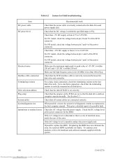
... troubleshooting Item Recommended work DC power cable Check that the power cable is correctly connected between the disk drive and controller. Interface cable connection Check that the SCSI interface cable is correctly connected to 5.25V DC. Plug setup Check that the jumpers on all system ...unstable, replace the power supply unit. For NP model, check the voltage between pin 1 and 2 of the SCSI connector. System cables Check that the disk drive and host computer operate normally. If the DC voltage level is probably not faulty. Check that the DC voltage ...
... troubleshooting Item Recommended work DC power cable Check that the power cable is correctly connected between the disk drive and controller. Interface cable connection Check that the SCSI interface cable is correctly connected to 5.25V DC. Plug setup Check that the jumpers on all system ...unstable, replace the power supply unit. For NP model, check the voltage between pin 1 and 2 of the SCSI connector. System cables Check that the disk drive and host computer operate normally. If the DC voltage level is probably not faulty. Check that the DC voltage ...


