Manual/User Guide
Page 4
... C141-E128-01EN Related Standards Specifications and functions of the Small Computer System Interface (SCSI) American National Standards Institute (ANSI) WORKING DRAFT Information Technology SCSI-3 Parallel Interface American National Standards Institute (ANSI) WORKING DRAFT Information American National technology SCSI Primary Commands-2 Standards Institute (SPC-2) (ANSI) American National Standard for American National Information Systems...
... C141-E128-01EN Related Standards Specifications and functions of the Small Computer System Interface (SCSI) American National Standards Institute (ANSI) WORKING DRAFT Information Technology SCSI-3 Parallel Interface American National Standards Institute (ANSI) WORKING DRAFT Information American National technology SCSI Primary Commands-2 Standards Institute (SPC-2) (ANSI) American National Standard for American National Information Systems...
Manual/User Guide
Page 5
... disk drive, connecting the cables, and confirming drive operation....install MAN series disk drives. It includes the ... scope of fixed disk drives and their standard features,...drives and discusses their use the other manuals. Chapter 8 PRINCIPLE OF OPERATION This chapter explains disk drives configuration and operation of the above disk drive...drives. Chapter 2 SPECIFICATIONS This chapter gives detailed specifications of troubleshooting the disk drives. Chapter 5 INSTALLATION This chapter explains how to do about media defects. PREFACE This manual describes the MAN3735MC...
... disk drive, connecting the cables, and confirming drive operation....install MAN series disk drives. It includes the ... scope of fixed disk drives and their standard features,...drives and discusses their use the other manuals. Chapter 8 PRINCIPLE OF OPERATION This chapter explains disk drives configuration and operation of the above disk drive...drives. Chapter 2 SPECIFICATIONS This chapter gives detailed specifications of troubleshooting the disk drives. Chapter 5 INSTALLATION This chapter explains how to do about media defects. PREFACE This manual describes the MAN3735MC...
Manual/User Guide
Page 6
... not perform the procedure correctly. Indicates iv C141-E128-01EN DANGER DANGER indicates that describes the electrical requirements of model names and product numbers, and SCSI interface functions. APPENDIX A to D The appendixes give supplementary information, including the locations of mounting setting terminals and connectors, a list of setting items, the signal assignments...
... not perform the procedure correctly. Indicates iv C141-E128-01EN DANGER DANGER indicates that describes the electrical requirements of model names and product numbers, and SCSI interface functions. APPENDIX A to D The appendixes give supplementary information, including the locations of mounting setting terminals and connectors, a list of setting items, the signal assignments...
Manual/User Guide
Page 7
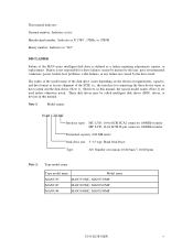
Fujitsu is defined as a failure requiring adjustments, repairs, or replacement. These disk drives may be called intelligent disk drives (IDD), drives, or devices in this manual. Hexadecimal number: Indicates as X'17B9', 17B9h, or 17B9H Binary number: Indicates as it is. The suffix of the model name of the disk drive... model name Type model name Model name MAN3735 MAN3735MC, MAN3735MP MAN3367 MAN3367MC, MAN3367MP MAN3184 MAN3184MC, MAN3184MP C141-E128-01EN v Hand Disk Drive Type AN: Number of the SCSI, i.e., the interface for drive failures caused by misuse by the user, poor...
Fujitsu is defined as a failure requiring adjustments, repairs, or replacement. These disk drives may be called intelligent disk drives (IDD), drives, or devices in this manual. Hexadecimal number: Indicates as X'17B9', 17B9h, or 17B9H Binary number: Indicates as it is. The suffix of the model name of the disk drive... model name Type model name Model name MAN3735 MAN3735MC, MAN3735MP MAN3367 MAN3367MC, MAN3367MP MAN3184 MAN3184MC, MAN3184MP C141-E128-01EN v Hand Disk Drive Type AN: Number of the SCSI, i.e., the interface for drive failures caused by misuse by the user, poor...
Manual/User Guide
Page 8
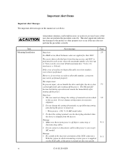
... DE and LSI become hot during the power is turned on, the overcurrent vi C141-E128-01EN Do not change the setting of the SCSI connectors. 5-11 With the system in minor or moderate personal injury if the user does not perform the procedure correctly. Important Alert Items Important... attached when the device is on . • Write protect: CN2 9-10 (MP model only) 3. Hot temperature To prevent injury, do not handle the drive until after the device has 5-1 cooled sufficiently after turning off the power. Alert message Page Data loss 2-5 For MAN series, Reed Solomon codes are as...
... DE and LSI become hot during the power is turned on, the overcurrent vi C141-E128-01EN Do not change the setting of the SCSI connectors. 5-11 With the system in minor or moderate personal injury if the user does not perform the procedure correctly. Important Alert Items Important... attached when the device is on . • Write protect: CN2 9-10 (MP model only) 3. Hot temperature To prevent injury, do not handle the drive until after the device has 5-1 cooled sufficiently after turning off the power. Alert message Page Data loss 2-5 For MAN series, Reed Solomon codes are as...
Manual/User Guide
Page 9
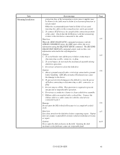
...not open the disk enclosure in the field because it is the last device connected to clean the disk drive. Fujitsu does not assume responsibility if data is destroyed during disk drive operation. 3. To avoid injury, do not touch the mechanical assembly during servicing or repair. Do not...Never open the DE in the field. Caution 6-6 1. Data loss 6-7 Save data stored on the disk drive before handling. C141-E128-01EN vii Caution 6-5 1. To connect SCSI devices, be prevented. 2. When the recommended parts listed in the wrong direction can be careful of the connection...
...not open the disk enclosure in the field because it is the last device connected to clean the disk drive. Fujitsu does not assume responsibility if data is destroyed during disk drive operation. 3. To avoid injury, do not touch the mechanical assembly during servicing or repair. Do not...Never open the DE in the field. Caution 6-6 1. Data loss 6-7 Save data stored on the disk drive before handling. C141-E128-01EN vii Caution 6-5 1. To connect SCSI devices, be prevented. 2. When the recommended parts listed in the wrong direction can be careful of the connection...
Manual/User Guide
Page 10
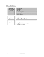
MANUAL ORGANIZATION PRODUCT/ MAINTENANCE MANUAL (This manual) 1. Installation Requirements 5. Diagnostics and Maintenance 7. Principle of Operation SCSI Physical Interface Specifications 1. SCSI Bus Error Recovery Processing SCSI Logical Interface Specifications 1. Sense Data and error Recovery Procedure 5. General Description 2. SCSI Message 3. Data Buffer Management 3. Command Specification 4. Disk Medium Management viii C141-E128-01EN SCSI Bus 2. Installation 6. Command Processing 2. Specifications 3. Data Format 4. Error Analysis 8.
MANUAL ORGANIZATION PRODUCT/ MAINTENANCE MANUAL (This manual) 1. Installation Requirements 5. Diagnostics and Maintenance 7. Principle of Operation SCSI Physical Interface Specifications 1. SCSI Bus Error Recovery Processing SCSI Logical Interface Specifications 1. Sense Data and error Recovery Procedure 5. General Description 2. SCSI Message 3. Data Buffer Management 3. Command Specification 4. Disk Medium Management viii C141-E128-01EN SCSI Bus 2. Installation 6. Command Processing 2. Specifications 3. Data Format 4. Error Analysis 8.
Manual/User Guide
Page 11
...Standard Features ...1-2 1.2 Hardware Structure...1-5 1.3 System Configuration ...1-8 CHAPTER 2 SPECIFICATIONS 2-1 2.1 Hardware Specifications 2-1 2.1.1 Model name and part number 2-1 2.1.2 Function specifications ...2-2 2.1.3 Environmental specifications 2-4 2.1.4 Error rate...2-5 2.1.5 Reliability ...2-5 2.2 SCSI Function Specifications 2-7 CHAPTER 3 DATA FORMAT 3-1 3.1 Data Space ...3-1 3.1.1 Cylinder configuration...3-1 3.1.2 Alternate spare area ...3-4 3.1.3 Track format ...3-5 3.1.4 Sector format ...3-7 3.1.5 Format capacity ...3-9 3.2 Logical Data Block Addressing 3-10 3.3 Defect...
...Standard Features ...1-2 1.2 Hardware Structure...1-5 1.3 System Configuration ...1-8 CHAPTER 2 SPECIFICATIONS 2-1 2.1 Hardware Specifications 2-1 2.1.1 Model name and part number 2-1 2.1.2 Function specifications ...2-2 2.1.3 Environmental specifications 2-4 2.1.4 Error rate...2-5 2.1.5 Reliability ...2-5 2.2 SCSI Function Specifications 2-7 CHAPTER 3 DATA FORMAT 3-1 3.1 Data Space ...3-1 3.1.1 Cylinder configuration...3-1 3.1.2 Alternate spare area ...3-4 3.1.3 Track format ...3-5 3.1.4 Sector format ...3-7 3.1.5 Format capacity ...3-9 3.2 Logical Data Block Addressing 3-10 3.3 Defect...
Manual/User Guide
Page 12
... Mounting procedures...5-10 5.5 Connecting Cables...5-11 5.6 Confirming Operations after Installation and Preparation for use 5-12 5.6.1 Confirming initial operations 5-12 5.6.2 Checking SCSI connection 5-13 5.6.3 Formatting ...5-16 5.6.4 Setting parameters ...5-18 5.7 Dismounting Drives...5-22 5.8 Spare Disk Drive ...5-22 CHAPTER 6 DIAGNOSTICS AND MAINTENANCE 6-1 6.1 Diagnostics ...6-1 6.1.1 Self-diagnostics ...6-1 6.1.2 Test programs ...6-4 6.2 Maintenance Information 6-5 6.2.1 Precautions ...6-5 6.2.2 Maintenance requirements 6-6 6.2.3 Maintenance levels ...6-8 6.2.4 Revision numbers...
... Mounting procedures...5-10 5.5 Connecting Cables...5-11 5.6 Confirming Operations after Installation and Preparation for use 5-12 5.6.1 Confirming initial operations 5-12 5.6.2 Checking SCSI connection 5-13 5.6.3 Formatting ...5-16 5.6.4 Setting parameters ...5-18 5.7 Dismounting Drives...5-22 5.8 Spare Disk Drive ...5-22 CHAPTER 6 DIAGNOSTICS AND MAINTENANCE 6-1 6.1 Diagnostics ...6-1 6.1.1 Self-diagnostics ...6-1 6.1.2 Test programs ...6-4 6.2 Maintenance Information 6-5 6.2.1 Precautions ...6-5 6.2.2 Maintenance requirements 6-6 6.2.3 Maintenance levels ...6-8 6.2.4 Revision numbers...
Manual/User Guide
Page 13
......6-12 Diagnostic test ...6-12 Troubleshooting Procedures 6-13 Outline of troubleshooting procedures 6-13 Troubleshooting with disk drive replacement in the field 6-13 Troubleshooting at the repair site 6-15 Troubleshooting with parts replacement in... (5-2x-xx), (5-3D-00), (5-90-00), (B-47-xx), (B-49-00), (B-4D-xx) and (B-4E-00): SCSI interface error 7-4 CHAPTER 8 PRINCIPLE OF OPERATION 8-1 8.1 Outline ...8-1 8.2 Disk Drive Configuration 8-1 8.2.1 Disks ...8-2 8.2.2 Heads ...8-2 8.2.3 Spindle mechanism...8-2 8.2.4 Actuator ...8-2 8.2.5 Air filters ...8-2 8.3 Circuit Configuration...8-3...
......6-12 Diagnostic test ...6-12 Troubleshooting Procedures 6-13 Outline of troubleshooting procedures 6-13 Troubleshooting with disk drive replacement in the field 6-13 Troubleshooting at the repair site 6-15 Troubleshooting with parts replacement in... (5-2x-xx), (5-3D-00), (5-90-00), (B-47-xx), (B-49-00), (B-4D-xx) and (B-4E-00): SCSI interface error 7-4 CHAPTER 8 PRINCIPLE OF OPERATION 8-1 8.1 Outline ...8-1 8.2 Disk Drive Configuration 8-1 8.2.1 Disks ...8-2 8.2.2 Heads ...8-2 8.2.3 Spindle mechanism...8-2 8.2.4 Actuator ...8-2 8.2.5 Air filters ...8-2 8.3 Circuit Configuration...8-3...
Manual/User Guide
Page 14
... Setting Terminals (MAN series MP model A-3 APPENDIX B SETTING TERMINALS B-1 B.1 Setting Terminals (MP model only B-2 APPENDIX C CONNECTOR SIGNAL ALLOCATION C-1 C.1 SCSI Connector Signal Allocation: SCA2 type LVD 16-bit SCSI C-2 C.2 SCSI Connector Signal Allocation: 68 pin type LVD 16-bit SCSI C-3 APPENDIX D MODEL NAMES AND PRODUCT NUMBERS D-1 D.1 Model Names and Product Numbers D-2 xii C141-E128-01EN
... Setting Terminals (MAN series MP model A-3 APPENDIX B SETTING TERMINALS B-1 B.1 Setting Terminals (MP model only B-2 APPENDIX C CONNECTOR SIGNAL ALLOCATION C-1 C.1 SCSI Connector Signal Allocation: SCA2 type LVD 16-bit SCSI C-2 C.2 SCSI Connector Signal Allocation: 68 pin type LVD 16-bit SCSI C-3 APPENDIX D MODEL NAMES AND PRODUCT NUMBERS D-1 D.1 Model Names and Product Numbers D-2 xii C141-E128-01EN
Manual/User Guide
Page 15
...AC noise filter (recommended 4-10 Figure 4.13 Connectors and terminals location (MP model 4-11 Figure 4.14 16-bit SCSI interface connector 4-11 Figure 4.15 Power supply connector (16-bit SCSI model 4-12 Figure 4.16 External operator panel connector (CN1 4-13 Figure 4.17 External operator panel connector (CN2 4-14... Figure 4.18 16-bit SCSI ID external input 4-15 Figure 4.19 Output signal for external LED 4-17 Figure 4.20 SCSI cables connection...4-18 Figure 4.21 Connectors location of MC model 4-19 C141-E128-01EN xiii
...AC noise filter (recommended 4-10 Figure 4.13 Connectors and terminals location (MP model 4-11 Figure 4.14 16-bit SCSI interface connector 4-11 Figure 4.15 Power supply connector (16-bit SCSI model 4-12 Figure 4.16 External operator panel connector (CN1 4-13 Figure 4.17 External operator panel connector (CN2 4-14... Figure 4.18 16-bit SCSI ID external input 4-15 Figure 4.19 Output signal for external LED 4-17 Figure 4.20 SCSI cables connection...4-18 Figure 4.21 Connectors location of MC model 4-19 C141-E128-01EN xiii
Manual/User Guide
Page 16
... connections (2 of 2 5-4 Figure 5.2 IDD setting terminals position 5-5 Figure 5.3 Setting terminals (CN2 MP model only 5-6 Figure 5.4 Checking the SCSI connection (A 5-14 Figure 5.5 Checking the SCSI connection (B 5-15 Figure 6.1 Revision label...6-9 Figure 6.2 Indicating revision numbers 6-10 Figure 6.3 Test flowchart ...6-11 Figure 7.1 Format of extended sense data 7-2 Figure 8.1 Circuit configuration ...8-4 Figure 8.2 IDD ...
... connections (2 of 2 5-4 Figure 5.2 IDD setting terminals position 5-5 Figure 5.3 Setting terminals (CN2 MP model only 5-6 Figure 5.4 Checking the SCSI connection (A 5-14 Figure 5.5 Checking the SCSI connection (B 5-15 Figure 6.1 Revision label...6-9 Figure 6.2 Indicating revision numbers 6-10 Figure 6.3 Test flowchart ...6-11 Figure 7.1 Format of extended sense data 7-2 Figure 8.1 Circuit configuration ...8-4 Figure 8.2 IDD ...
Manual/User Guide
Page 17
... 6.1 Self-diagnostic functions...6-1 Table 6.2 System-level field troubleshooting 6-14 Table 6.3 Disk drive troubleshooting...6-15 Table 7.1 Definition of sense data...7-3 Table B.1 Setting terminal: CN2 ...B-2 Table C.1 SCSI connector (SCA2 type LVD 16-bit SCSI): CN1 C-2 Table C.2 SCSI connector (68 pin type LVD 16-bit SCSI): CN1 C-3 Table D.1 MAN series model names and product numbers D-2 C141-E128-01EN...
... 6.1 Self-diagnostic functions...6-1 Table 6.2 System-level field troubleshooting 6-14 Table 6.3 Disk drive troubleshooting...6-15 Table 7.1 Definition of sense data...7-3 Table B.1 Setting terminal: CN2 ...B-2 Table C.1 SCSI connector (SCA2 type LVD 16-bit SCSI): CN1 C-2 Table C.2 SCSI connector (68 pin type LVD 16-bit SCSI): CN1 C-3 Table D.1 MAN series model names and product numbers D-2 C141-E128-01EN...
Manual/User Guide
Page 19
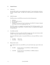
... to construct a high-performance reliable disk subsystem with an embedded SCSI controller. C141-E128-01EN 1 - 1 The flexibility and expandability of the SCSI, as well as the powerful command set of the intelligent disk drives (IDD). CHAPTER 1 GENERAL DESCRIPTION 1.1 Standard Features 1.2 Hardware Structure... chapter describes the feature and configuration of the IDD, allow the user to SCSI Logical Interface Specifications for details. IDDs are high performance large capacity 3.5 type fixed disk drives with large storage capacity. The interface between the IDD and host system is ...
... to construct a high-performance reliable disk subsystem with an embedded SCSI controller. C141-E128-01EN 1 - 1 The flexibility and expandability of the SCSI, as well as the powerful command set of the intelligent disk drives (IDD). CHAPTER 1 GENERAL DESCRIPTION 1.1 Standard Features 1.2 Hardware Structure... chapter describes the feature and configuration of the IDD, allow the user to SCSI Logical Interface Specifications for details. IDDs are high performance large capacity 3.5 type fixed disk drives with large storage capacity. The interface between the IDD and host system is ...
Manual/User Guide
Page 20
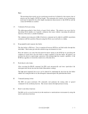
... to accommodate future expansion of system functions. (3) 8-bit SCSI/16-bit SCSI The IDD has 16-bit data bus width (16-bit SCSI), which meets the logical specification of connectable SCSI devices on the same SCSI bus is varied as follows. • 8-bit SCSI: 8 drives max. • 16-bit SCSI: 16 drives max. (4) High speed data transfer Such a high...
... to accommodate future expansion of system functions. (3) 8-bit SCSI/16-bit SCSI The IDD has 16-bit data bus width (16-bit SCSI), which meets the logical specification of connectable SCSI devices on the same SCSI bus is varied as follows. • 8-bit SCSI: 8 drives max. • 16-bit SCSI: 16 drives max. (4) High speed data transfer Such a high...
Manual/User Guide
Page 21
... data access can be achieved, and IDD can perform the effective input/output operations with utilizing high data transfer capability of the SCSI bus regardless of actual data transfer rate of the data buffer, the initiator can perform continuous read/write operation when processing data ... concerning the physical structure of queued commands by specifying the condition of stored data to the data buffer or empty condition of the disk drive. (7) Read-ahead cache feature After executing the READ command, the IDD reads automatically and stores (prefetches) the subsequent data blocks into ...
... data access can be achieved, and IDD can perform the effective input/output operations with utilizing high data transfer capability of the SCSI bus regardless of actual data transfer rate of the data buffer, the initiator can perform continuous read/write operation when processing data ... concerning the physical structure of queued commands by specifying the condition of stored data to the data buffer or empty condition of the disk drive. (7) Read-ahead cache feature After executing the READ command, the IDD reads automatically and stores (prefetches) the subsequent data blocks into ...
Manual/User Guide
Page 22
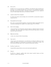
...the IDD can automatically reassign its powerful retry processing. (10) Error recovery The IDD can try to recover from errors in SCSI bus or the disk drive using its alternate data block. (12) Programmable data block length Data can be accessed in fixed-block length units. This ...-free data can start and stop the spindle motor. (17) Diagnosis The IDD has a diagnostic capability which checks internal controller functions and drive operations to 528 bytes. (13) Defective block slipping A logical data block can be obtained from the complicated error recover processing by dividing all...
...the IDD can automatically reassign its powerful retry processing. (10) Error recovery The IDD can try to recover from errors in SCSI bus or the disk drive using its alternate data block. (12) Programmable data block length Data can be accessed in fixed-block length units. This ...-free data can start and stop the spindle motor. (17) Diagnosis The IDD has a diagnostic capability which checks internal controller functions and drive operations to 528 bytes. (13) Defective block slipping A logical data block can be obtained from the complicated error recover processing by dividing all...
Manual/User Guide
Page 26
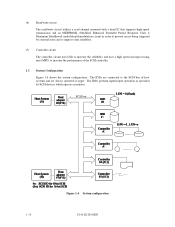
... uses LSIs to increase the reliability and uses a high speed microprocessing unit (MPU) to the SCSI bus of host systems and are connected to increase the performance of the SCSI controller. 1.3 System Configuration Figure 1.4 shows the system configuration. SCSI bus Figure 1.4 System configuration 1 - 8 C141-E128-01EN The IDDs are always operated as initiator...high-speed transmission and an MEEPR4ML (Modified Enhanced Extended Partial Response Class 4 Maximum Likelihood) modulation/demodulation circuit in order to prevent errors being triggered by SCSI devices which operate as target.
... uses LSIs to increase the reliability and uses a high speed microprocessing unit (MPU) to the SCSI bus of host systems and are connected to increase the performance of the SCSI controller. 1.3 System Configuration Figure 1.4 shows the system configuration. SCSI bus Figure 1.4 System configuration 1 - 8 C141-E128-01EN The IDDs are always operated as initiator...high-speed transmission and an MEEPR4ML (Modified Enhanced Extended Partial Response Class 4 Maximum Likelihood) modulation/demodulation circuit in order to prevent errors being triggered by SCSI devices which operate as target.
Manual/User Guide
Page 27
...A unique address (LUN: logical unit number) is a single logical unit, the selectable number of SCSI ID and LUN are as follows: • SCSI ID: • LUN: 8-bit SCSI:Selectable from 0 to 7 (switch selectable) 16-bit SCSI:Selectable from 0 to 15 (switch selectable) 0 (fixed) C141-E128-01EN 1 - 9 For...possible on multiSCSI devices. (2) Addressing of peripheral device Each SCSI device on which multiple host computers that the whole volume of disk drive is assigned for each logical unit. (1) SCSI bus configuration Up to eight SCSI devices operating as an initiator or a target can be ...
...A unique address (LUN: logical unit number) is a single logical unit, the selectable number of SCSI ID and LUN are as follows: • SCSI ID: • LUN: 8-bit SCSI:Selectable from 0 to 7 (switch selectable) 16-bit SCSI:Selectable from 0 to 15 (switch selectable) 0 (fixed) C141-E128-01EN 1 - 9 For...possible on multiSCSI devices. (2) Addressing of peripheral device Each SCSI device on which multiple host computers that the whole volume of disk drive is assigned for each logical unit. (1) SCSI bus configuration Up to eight SCSI devices operating as an initiator or a target can be ...

