Manual/User Guide
Page 5
... describes diagnostic methods for setting device number and operation modes, mounting the disk drive, connecting the cables, and confirming drive operation. It includes the notice and procedures for operation check and the basics of this manual. The need arises, use in details how collect the information for installing MAN series disk drives. Chapter 4 INSTALLATION REQUIREMENTS This chapter describes the basic physical and electrical requirements for error analysis and how analyze collected error information. Chapter 7 ERROR ANALYSIS...
... describes diagnostic methods for setting device number and operation modes, mounting the disk drive, connecting the cables, and confirming drive operation. It includes the notice and procedures for operation check and the basics of this manual. The need arises, use in details how collect the information for installing MAN series disk drives. Chapter 4 INSTALLATION REQUIREMENTS This chapter describes the basic physical and electrical requirements for error analysis and how analyze collected error information. Chapter 7 ERROR ANALYSIS...
Manual/User Guide
Page 7
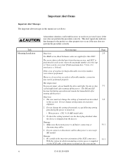
... connecting the three device types or host system and the disk drives (Note 1). Hand Disk Drive Type AN: Number of the SCSI, i.e., the interface for drive failures caused by misuse by the user, poor environmental conditions, power trouble, host problems, cable failures, or any failure not caused by the drive itself. Note 1: Model names M AN 3 735 MC Interface types MC: LVD, 16-bit SCSI SCA2 connector 160MHz transfer MP: LVD, 16-bit SCSI 68 pin connector 160MHz transfer Formatted capacity (100 MB units) Disk drive size 3: 3.5 type...
... connecting the three device types or host system and the disk drives (Note 1). Hand Disk Drive Type AN: Number of the SCSI, i.e., the interface for drive failures caused by misuse by the user, poor environmental conditions, power trouble, host problems, cable failures, or any failure not caused by the drive itself. Note 1: Model names M AN 3 735 MC Interface types MC: LVD, 16-bit SCSI SCA2 connector 160MHz transfer MP: LVD, 16-bit SCSI 68 pin connector 160MHz transfer Formatted capacity (100 MB units) Disk drive size 3: 3.5 type...
Manual/User Guide
Page 8
... change the setting of terminals except following setting pins during operation and remain hot immediately after turning off the power. Do not change the setting of terminals not described 5-5 in which terminating resistor power is supplied via the SCSI cable, if the power is turned on .(except MC model) Damage 1. Make sure that damages to 5 byte) can be performed properly. However, if error byte exceeds its allowable number...
... change the setting of terminals except following setting pins during operation and remain hot immediately after turning off the power. Do not change the setting of terminals not described 5-5 in which terminating resistor power is supplied via the SCSI cable, if the power is turned on .(except MC model) Damage 1. Make sure that damages to 5 byte) can be performed properly. However, if error byte exceeds its allowable number...
Manual/User Guide
Page 14
... format...8-12 Spindle motor control ...8-12 Voice coil motor control 8-13 APPENDIX A LOCATIONS OF CONNECTORS AND SETTING TERMINALS A-1 A.1 Locations of Connectors and Setting Terminals (MAH series MC model A-2 A.2 Locations of Connectors and Setting Terminals (MAN series MP model A-3 APPENDIX B SETTING TERMINALS B-1 B.1 Setting Terminals (MP model only B-2 APPENDIX C CONNECTOR SIGNAL ALLOCATION C-1 C.1 SCSI Connector Signal Allocation: SCA2 type LVD 16-bit SCSI C-2 C.2 SCSI Connector Signal Allocation: 68 pin type LVD 16-bit SCSI C-3 APPENDIX D MODEL NAMES AND PRODUCT NUMBERS...
... format...8-12 Spindle motor control ...8-12 Voice coil motor control 8-13 APPENDIX A LOCATIONS OF CONNECTORS AND SETTING TERMINALS A-1 A.1 Locations of Connectors and Setting Terminals (MAH series MC model A-2 A.2 Locations of Connectors and Setting Terminals (MAN series MP model A-3 APPENDIX B SETTING TERMINALS B-1 B.1 Setting Terminals (MP model only B-2 APPENDIX C CONNECTOR SIGNAL ALLOCATION C-1 C.1 SCSI Connector Signal Allocation: SCA2 type LVD 16-bit SCSI C-2 C.2 SCSI Connector Signal Allocation: 68 pin type LVD 16-bit SCSI C-3 APPENDIX D MODEL NAMES AND PRODUCT NUMBERS...
Manual/User Guide
Page 17
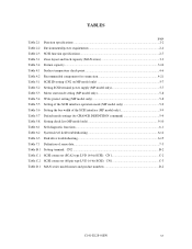
... Setting SCSI terminal power supply (MP model only 5-7 Table 5.3 Motor start mode setting (MP model only 5-8 Table 5.4 Write protect setting (MP model only 5-8 Table 5.5 Setting of the SCSI interface operation mode (MP model only 5-9 Table 5.6 Setting the bus width of the SCSI interface (MP model only 5-9 Table 5.7 Default mode settings (by CHANGE DEFINITION command 5-9 Table 5.8 Setting check list (MP model only 5-10 Table 6.1 Self-diagnostic functions...6-1 Table 6.2 System-level field troubleshooting 6-14 Table 6.3 Disk drive troubleshooting...6-15 Table 7.1 Definition of sense data...
... Setting SCSI terminal power supply (MP model only 5-7 Table 5.3 Motor start mode setting (MP model only 5-8 Table 5.4 Write protect setting (MP model only 5-8 Table 5.5 Setting of the SCSI interface operation mode (MP model only 5-9 Table 5.6 Setting the bus width of the SCSI interface (MP model only 5-9 Table 5.7 Default mode settings (by CHANGE DEFINITION command 5-9 Table 5.8 Setting check list (MP model only 5-10 Table 6.1 Self-diagnostic functions...6-1 Table 6.2 System-level field troubleshooting 6-14 Table 6.3 Disk drive troubleshooting...6-15 Table 7.1 Definition of sense data...
Manual/User Guide
Page 30
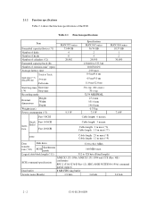
... Item Formatted capacity/device (*1) Number of disks Number of heads Number of cylinders (*2) Formatted capacity/track (B) Number of the IDD. Fast 10 SCSI Inter- 2.1.2 Function specifications Table 2.1 shows the function specifications of rotations min-1 (rpm) Average latency time Seek time (*3) (Read/Write) Track to Track Average Full stroke Start/stop time Start time (*4) Stop time Recording mode External dimensions Height: Width: Depth: Weight (max) Power consumption (*5) Fast 5 SCSI MAN3735 series 73.49 GB 4 8 29,902 9.5 W Specification MAN3367 series 36.74 GB 2 4 29...
... Item Formatted capacity/device (*1) Number of disks Number of heads Number of cylinders (*2) Formatted capacity/track (B) Number of the IDD. Fast 10 SCSI Inter- 2.1.2 Function specifications Table 2.1 shows the function specifications of rotations min-1 (rpm) Average latency time Seek time (*3) (Read/Write) Track to Track Average Full stroke Start/stop time Start time (*4) Stop time Recording mode External dimensions Height: Width: Depth: Weight (max) Power consumption (*5) Fast 5 SCSI MAN3735 series 73.49 GB 4 8 29,902 9.5 W Specification MAN3367 series 36.74 GB 2 4 29...
Manual/User Guide
Page 31
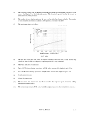
... the time from power on 1 connection case. (*9) 1 host, 15 devices case. (*10) The maximum data transfer rate may be restricted to the response speed of initiator and by transmission characteristics. (*11) The terminator power pin (SCSI connector) which supplies power to other terminators is an estimate for 512 bytes per sector. (*2) The number of 25pF or less can be changed by changing the logical block length and using spare sector space. The formatted capacity...
... the time from power on 1 connection case. (*9) 1 host, 15 devices case. (*10) The maximum data transfer rate may be restricted to the response speed of initiator and by transmission characteristics. (*11) The terminator power pin (SCSI connector) which supplies power to other terminators is an estimate for 512 bytes per sector. (*2) The number of 25pF or less can be changed by changing the logical block length and using spare sector space. The formatted capacity...
Manual/User Guide
Page 33
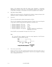
... temperature: 40°C or less). Note: The MTBF is defined as: MTBF= Operating time (hours) at the connector. (*6) The terminator power pin (SCSI connector) which can be corrected. [Total maximum byte: 5 byte × 6 ( interleave) = 30 byte] If the error of read sector keeps allowable error byte number, correction is performed in the error rate. The sector-data is divided into 6 interleaving sectors, and ECC is performed. CAUTION Data loss For MAN series, Reed Solomon codes...
... temperature: 40°C or less). Note: The MTBF is defined as: MTBF= Operating time (hours) at the connector. (*6) The terminator power pin (SCSI connector) which can be corrected. [Total maximum byte: 5 byte × 6 ( interleave) = 30 byte] If the error of read sector keeps allowable error byte number, correction is performed in the error rate. The sector-data is divided into 6 interleaving sectors, and ECC is performed. CAUTION Data loss For MAN series, Reed Solomon codes...
Manual/User Guide
Page 34
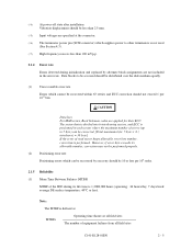
... repair, adjustments, or replacement. Note: The "average DE surface temperature" means the average temperature at the DE surface throughout the year when the IDD is operating. (4) Data security at power failure Integrity of the data on the disk is being performed. The above does not applied to formatting disks or assigning alternate blocks. 2 - 6 C141-E035-02EN Even if the IDD is used intermittently, the longest service...
... repair, adjustments, or replacement. Note: The "average DE surface temperature" means the average temperature at the DE surface throughout the year when the IDD is operating. (4) Data security at power failure Integrity of the data on the disk is being performed. The above does not applied to formatting disks or assigning alternate blocks. 2 - 6 C141-E035-02EN Even if the IDD is used intermittently, the longest service...
Manual/User Guide
Page 59
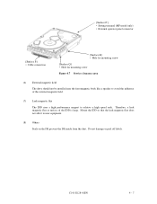
[Surface P'] • Setting terminal (MP model only) • External operator panel connector [Surface P] • Cable connection [Surface R] • Hole for mounting screw [Surface Q] • Hole for mounting screw Figure 4.7 Service clearance area (6) External magnetic field The drive should not be installed near equipment. (8) Others...body like a speaker to achieve a high speed seek. C141-E128-01EN 4 - 7 Therefore, a leak magnetic flux at surface of the external magnetic field. (7) Leak magnetic flux The IDD uses a high performance magnet to avoid the influence of the IDD...
[Surface P'] • Setting terminal (MP model only) • External operator panel connector [Surface P] • Cable connection [Surface R] • Hole for mounting screw [Surface Q] • Hole for mounting screw Figure 4.7 Service clearance area (6) External magnetic field The drive should not be installed near equipment. (8) Others...body like a speaker to achieve a high speed seek. C141-E128-01EN 4 - 7 Therefore, a leak magnetic flux at surface of the external magnetic field. (7) Leak magnetic flux The IDD uses a high performance magnet to avoid the influence of the IDD...
Manual/User Guide
Page 75
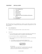
... in a dirty or contaminated environment. CAUTION Hot temperature To prevent injury, do not handle the drive until after the device has cooled sufficiently after turning off the power. Do not touch PCAs except for use, and dismounting drives. 5.1 Notes on handling drives, connections, setting switches and plugs, mounting drives, connecting cables, confirming drive operations after installation and preparation for setting. C141-E128-01EN 5 - 1 c) Since static discharge...
... in a dirty or contaminated environment. CAUTION Hot temperature To prevent injury, do not handle the drive until after the device has cooled sufficiently after turning off the power. Do not touch PCAs except for use, and dismounting drives. 5.1 Notes on handling drives, connections, setting switches and plugs, mounting drives, connecting cables, confirming drive operations after installation and preparation for setting. C141-E128-01EN 5 - 1 c) Since static discharge...
Manual/User Guide
Page 76
... and keep removed screws and other parts where they are pins 9, 10 (Write Protect) in CN2. (MP model) b) Do not move the drive when power is turned on . d) Keep a record of the package so that the drive is up. (2) Unpackaging a) Use a flat work for replacing. (4) Packaging a) Store the drive in an antistatic vinyl pack. In this case, fully protect the PCAs and interface connector so...
... and keep removed screws and other parts where they are pins 9, 10 (Write Protect) in CN2. (MP model) b) Do not move the drive when power is turned on . d) Keep a record of the package so that the drive is up. (2) Unpackaging a) Use a flat work for replacing. (4) Packaging a) Store the drive in an antistatic vinyl pack. In this case, fully protect the PCAs and interface connector so...
Manual/User Guide
Page 90
... connectors including other SCSI devices are as follows. c) Check the setting of data blocks" field. Refer to Chapter 5 of SCSI Logical Interface Specifications for each model (part number) when shipped from the default format, all sides of the logical data block in the user space • Alternate spare area size This section outlines the formatting at abnormal end a) When sense data can change the following items for a recoverable error. The parameters...
... connectors including other SCSI devices are as follows. c) Check the setting of data blocks" field. Refer to Chapter 5 of SCSI Logical Interface Specifications for each model (part number) when shipped from the default format, all sides of the logical data block in the user space • Alternate spare area size This section outlines the formatting at abnormal end a) When sense data can change the following items for a recoverable error. The parameters...
Manual/User Guide
Page 92
... best performance, set the parameters in this section is not affected. 4. In the multi-INIT System, parameter setting cannot be set or saved with the MODE SELECT or MODE SELECT EXTENDED command, the IDD sets the default values for parameters and operates when power is not executed at installation. 5 - 18 C141-E128-01EN When the parameters are assured with the MODE SELECT or MODE SELECT EXTENDED command: • Error recovery parameter • Disconnection/reconnection parameter • Caching parameter • Control mode parameter...
... best performance, set the parameters in this section is not affected. 4. In the multi-INIT System, parameter setting cannot be set or saved with the MODE SELECT or MODE SELECT EXTENDED command, the IDD sets the default values for parameters and operates when power is not executed at installation. 5 - 18 C141-E128-01EN When the parameters are assured with the MODE SELECT or MODE SELECT EXTENDED command: • Error recovery parameter • Disconnection/reconnection parameter • Caching parameter • Control mode parameter...
Manual/User Guide
Page 94
... amount of processing data specified with a command Refer to Chapter 2 of SCSI Logical Interface Specifications for how to transfer data on the SCSI bus at a read (READ or READ EXTENDED command) or write operation (WRITE, WRITE EXTENDED, or WRITE AND VERIFY command) of the specified values by measuring performance in normal operations. (2) Disconnection/reconnection parameters (page code = 2) The following parameters according to be specified. 2. It is recommended to use the default setting in an operation status under...
... amount of processing data specified with a command Refer to Chapter 2 of SCSI Logical Interface Specifications for how to transfer data on the SCSI bus at a read (READ or READ EXTENDED command) or write operation (WRITE, WRITE EXTENDED, or WRITE AND VERIFY command) of the specified values by measuring performance in normal operations. (2) Disconnection/reconnection parameters (page code = 2) The following parameters according to be specified. 2. It is recommended to use the default setting in an operation status under...
Manual/User Guide
Page 103
... model, part number (P/N), revision number, serial number (S/N), and date of manufacturing b) Error status • Date when the error occurred • System configuration • Environmental conditions (temperature, humidity, and voltage) c) Error history d) Error contents • Outline of inconvenience • Issued commands and specified parameters • Sense data • Other error analysis information CAUTION Data loss Save data stored on the disk drive before requesting repair. Generally, the following information must be replaced in the field. (4) Service system and repairs...
... model, part number (P/N), revision number, serial number (S/N), and date of manufacturing b) Error status • Date when the error occurred • System configuration • Environmental conditions (temperature, humidity, and voltage) c) Error history d) Error contents • Outline of inconvenience • Issued commands and specified parameters • Sense data • Other error analysis information CAUTION Data loss Save data stored on the disk drive before requesting repair. Generally, the following information must be replaced in the field. (4) Service system and repairs...
Manual/User Guide
Page 110
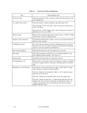
...-level field troubleshooting Item DC power cable AC and DC power level Electrical noise Interface cable connection Terminating resistors Drive selection address Plug setup System cables System diagnostic test Intermittent or nonfatal errors Recommended work Check that the power cable is correctly connected to 5.25 VDC. Check that the +5 VDC value (pins 3 and 4 of the error. Check that the DC voltage is set so that the +12 VDC supply (pins 1 and 2 of the power connector of...
...-level field troubleshooting Item DC power cable AC and DC power level Electrical noise Interface cable connection Terminating resistors Drive selection address Plug setup System cables System diagnostic test Intermittent or nonfatal errors Recommended work Check that the power cable is correctly connected to 5.25 VDC. Check that the +5 VDC value (pins 3 and 4 of the error. Check that the DC voltage is set so that the +12 VDC supply (pins 1 and 2 of the power connector of...
Manual/User Guide
Page 111
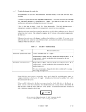
... 6.3 Disk drive troubleshooting Item Frequent or repeated seek errors Intermittent or nonfatal errors Recommended action Collect sense data, and see Chapter 7. This is used. Chapter 7 error analysis by changing the voltage or temperature. If no error occurs in an ordinary test, disk drive conditions can be included with a disk drive returned to recur. If the disk drive error recurs or a possibly faulty part is the disk enclosure, return the whole disk drive to the factory for repair. 6.4.3 Troubleshooting at...
... 6.3 Disk drive troubleshooting Item Frequent or repeated seek errors Intermittent or nonfatal errors Recommended action Collect sense data, and see Chapter 7. This is used. Chapter 7 error analysis by changing the voltage or temperature. If no error occurs in an ordinary test, disk drive conditions can be included with a disk drive returned to recur. If the disk drive error recurs or a possibly faulty part is the disk enclosure, return the whole disk drive to the factory for repair. 6.4.3 Troubleshooting at...
Manual/User Guide
Page 129
... control provides return-to-zero (RTZ) operation, seek operation, and track following operation To read /write request, the MPU issues a seek command to the DSP to move . When the DSP receives this command, the DSP drives the voice coil motor, via the digital-to-analog converter and power amplifier, to move to a disk, the head must be correctly centered over the target cylinder. A predetermined target speed is...
... control provides return-to-zero (RTZ) operation, seek operation, and track following operation To read /write request, the MPU issues a seek command to the DSP to move . When the DSP receives this command, the DSP drives the voice coil motor, via the digital-to-analog converter and power amplifier, to move to a disk, the head must be correctly centered over the target cylinder. A predetermined target speed is...
Manual/User Guide
Page 136
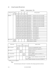
.../STOP command Short Started by turning the power supply on (*) Force Narrow Open Width of 16 bit bus (*) Short Width of 8 bit bus Force Single Ended Open Follows DIFFSNS signal level on SCSI bus (*) Short Single-Ended mode Terminating power supply Open Does not supply terminating resistor power to SCSI BUS * Setting at factory shipment Short Supply terminating resistor power to 8-bit and 16-bit SCSI) Short Open Open Open SCSI ID...
.../STOP command Short Started by turning the power supply on (*) Force Narrow Open Width of 16 bit bus (*) Short Width of 8 bit bus Force Single Ended Open Follows DIFFSNS signal level on SCSI bus (*) Short Single-Ended mode Terminating power supply Open Does not supply terminating resistor power to SCSI BUS * Setting at factory shipment Short Supply terminating resistor power to 8-bit and 16-bit SCSI) Short Open Open Open SCSI ID...


