English Manual.
Page 18
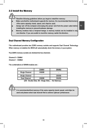
... Channel 1 : DIMM2 The combinations of the same capacity, brand, speed, and chips be used . ■ Always turn off the computer and unplug the power cord from the power outlet before you are : Single Channel DIMM1 DS/SS DIMM2 - Read the following guidelines before installing the memory to achieve optimum performance. It is... be used and please select dual channel first to prevent hardware damage. ■ Memory modules have a foolproof design. If you begin to insert the memory, switch the direction. CAUTION 11 11
... Channel 1 : DIMM2 The combinations of the same capacity, brand, speed, and chips be used . ■ Always turn off the computer and unplug the power cord from the power outlet before you are : Single Channel DIMM1 DS/SS DIMM2 - Read the following guidelines before installing the memory to achieve optimum performance. It is... be used and please select dual channel first to prevent hardware damage. ■ Memory modules have a foolproof design. If you begin to insert the memory, switch the direction. CAUTION 11 11
English Manual.
Page 23
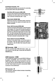
... 4 GND 5 IRTX IR This 2-pin connector is off rather than using the power supply button. Reset Switch (RESET-SW) Attach the connector to the Reset switch on . When the system is in S3/ S4 sleep state or power off mode (S5), the LED is directional with COM2 connector in the motherboard.... the system to connect with +/- Hard Disk LED Connector (HDD-LED) Connect to the power button on the front panel of the chassis. The Power LED indicates the system's status. Power Switch Connector (PWR-SW) Connect to the chassis front panel IDE indicator LED. 2 Front Panel Connector : FP1 This ...
... 4 GND 5 IRTX IR This 2-pin connector is off rather than using the power supply button. Reset Switch (RESET-SW) Attach the connector to the Reset switch on . When the system is in S3/ S4 sleep state or power off mode (S5), the LED is directional with COM2 connector in the motherboard.... the system to connect with +/- Hard Disk LED Connector (HDD-LED) Connect to the power button on the front panel of the chassis. The Power LED indicates the system's status. Power Switch Connector (PWR-SW) Connect to the chassis front panel IDE indicator LED. 2 Front Panel Connector : FP1 This ...


