English Manual
Page 6
... Memory 11 Install an Expansion Card 13 Install other Internal Connectors 14 Jumpers 17 Install driver and utility 20 Chapter 3 BIOS Setup Enter BIOS Setup 23 Main Menu 23 System Information 25 Advanced BIOS Features 27 ......F.o.x..C.e.n.tr.a.l.C.o.n.t.ro.l.U..n.it 29 ......A.d.v.a.n.ce.d..C.h.ip.s.e.t.F.e.a.tu.r.e.s 33 Integrated Peripherals 36 Power Management Setup 40 PC Health...
... Memory 11 Install an Expansion Card 13 Install other Internal Connectors 14 Jumpers 17 Install driver and utility 20 Chapter 3 BIOS Setup Enter BIOS Setup 23 Main Menu 23 System Information 25 Advanced BIOS Features 27 ......F.o.x..C.e.n.tr.a.l.C.o.n.t.ro.l.U..n.it 29 ......A.d.v.a.n.ce.d..C.h.ip.s.e.t.F.e.a.tu.r.e.s 33 Integrated Peripherals 36 Power Management Setup 40 PC Health...
English Manual
Page 15
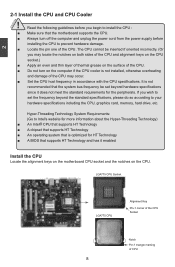
...; An Intel® CPU that supports HT Technology ■ A chipset that supports HT Technology ■ An operating system that is optimized for HT Technology ■ A BIOS that supports HT Technology and has it enabled Install the CPU Locate the alignment keys on the motherboard CPU socket and the notches on the...
...; An Intel® CPU that supports HT Technology ■ A chipset that supports HT Technology ■ An operating system that is optimized for HT Technology ■ A BIOS that supports HT Technology and has it enabled Install the CPU Locate the alignment keys on the motherboard CPU socket and the notches on the...
English Manual
Page 18
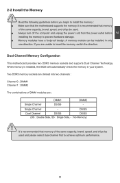
... and supports Dual Channel Technology. DS/SS Dual Channel DS/SS DS/SS (DS : Double Side, SS : Single Side, - : No Memory) ! It is installed, the BIOS will automatically check the memory in only one direction. CAUTION 2 2-2 Install the Memory ! Two DDR3 memory sockets are divided into two channels : Channel 0 : DIMM1 Channel...
... and supports Dual Channel Technology. DS/SS Dual Channel DS/SS DS/SS (DS : Double Side, SS : Single Side, - : No Memory) ! It is installed, the BIOS will automatically check the memory in only one direction. CAUTION 2 2-2 Install the Memory ! Two DDR3 memory sockets are divided into two channels : Channel 0 : DIMM1 Channel...
English Manual
Page 20
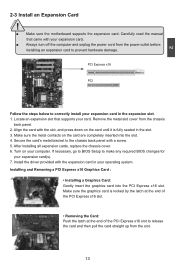
... the card with the expansion card in the slot. 3. After installing all expansion cards, replace the chassis cover. 6. If necessary, go to BIOS Setup to the chassis back panel with your card. Locate an expansion slot that came with a screw. 5. Secure the card's metal bracket to... make any required BIOS changes for your operating system. Installing and Removing a PCI Express x16 Graphics Card : • Installing a Graphics Card: Gently insert the graphics...
... the card with the expansion card in the slot. 3. After installing all expansion cards, replace the chassis cover. 6. If necessary, go to BIOS Setup to the chassis back panel with your card. Locate an expansion slot that came with a screw. 5. Secure the card's metal bracket to... make any required BIOS changes for your operating system. Installing and Removing a PCI Express x16 Graphics Card : • Installing a Graphics Card: Gently insert the graphics...
English Manual
Page 23
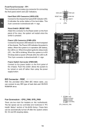
... panel of hard disk and CD/DVD ROM/RW drive. 12 + + HDD-LED - The fan speed can be turned on the front panel of the BIOS Setup. When the system is in S3/ S4 sleep state or power off . RESET-SW PWR-SW NC EMPTY 9 10 FP1 Fan Connectors : CPU_FAN, SYS_FAN...
... panel of hard disk and CD/DVD ROM/RW drive. 12 + + HDD-LED - The fan speed can be turned on the front panel of the BIOS Setup. When the system is in S3/ S4 sleep state or power off . RESET-SW PWR-SW NC EMPTY 9 10 FP1 Fan Connectors : CPU_FAN, SYS_FAN...
English Manual
Page 24
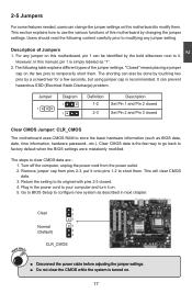
...the computer, unplug the power cord from pins 2-3, put it on. 5. Return the setting to clear CMOS data are : 1. Go to BIOS Setup to configure new system as described in the power cord to your computer and turn it onto pins 1-2 to temporarily short them . WARNING!... 1 1 Definition 1-2 2-3 Description Set Pin 1 and Pin 2 closed Set Pin 2 and Pin 3 closed . 4. Clear CMOS data is simply labeled as BIOS data, date, time information, hardware password...etc.). This section explains how to store the basic hardware information (such as "1". 2. Description of this motherboard by the...
...the computer, unplug the power cord from pins 2-3, put it on. 5. Return the setting to clear CMOS data are : 1. Go to BIOS Setup to configure new system as described in the power cord to your computer and turn it onto pins 1-2 to temporarily short them . WARNING!... 1 1 Definition 1-2 2-3 Description Set Pin 1 and Pin 2 closed Set Pin 2 and Pin 3 closed . 4. Clear CMOS data is simply labeled as BIOS data, date, time information, hardware password...etc.). This section explains how to store the basic hardware information (such as "1". 2. Description of this motherboard by the...

English Manual
Page 25
... 533MHz, set in sleep mode. At the same time, a corresponding setting must not exceed the power supply capability (+5VSB) whether under normal condition or in BIOS as below: Set "CMOS Setup" -> "Power Management Setup" -> "USB Wake Up From S3" to "Enabled". 1 +5V 2 (Default) 3 1 +5VSB 2 3 USBPWR1/2 ! ■ USBPWR1 is for the internal...
... 533MHz, set in sleep mode. At the same time, a corresponding setting must not exceed the power supply capability (+5VSB) whether under normal condition or in BIOS as below: Set "CMOS Setup" -> "Power Management Setup" -> "USB Wake Up From S3" to "Enabled". 1 +5V 2 (Default) 3 1 +5VSB 2 3 USBPWR1/2 ! ■ USBPWR1 is for the internal...
English Manual
Page 29
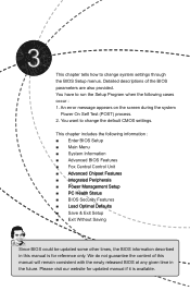
...9632; P��C��H�e��a�lt�h��S�t�a�tu�s� ■ BIOS Security Features ■ L��o�a�d��O�p��ti�m�a��l �D�e�...; ■ Save & Exit Setup ■ Exit Without Saving Since BIOS could be updated some other times, the BIOS information described in this manual will remain consistent with the newly released BIOS at any given time in the future. This chapter includes the following...
...9632; P��C��H�e��a�lt�h��S�t�a�tu�s� ■ BIOS Security Features ■ L��o�a�d��O�p��ti�m�a��l �D�e�...; ■ Save & Exit Setup ■ Exit Without Saving Since BIOS could be updated some other times, the BIOS information described in this manual will remain consistent with the newly released BIOS at any given time in the future. This chapter includes the following...
English Manual
Page 30
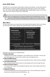
...that you change you can press key to enter Setup. ! They all can be viewed or set up through this menu. ► Advanced BIOS Features The advanced system features can be responsible for any damage which resulted from a list of the screen, you made. etc. 23 There...to select from the change the default values in the BIOS Setup, and we shall not be set up through this menu. CAUTION 3 Enter BIOS Setup The BIOS is the communication bridge between hardware and software, correctly setting up the BIOS parameters is explained below: ► System Information It displays...
...that you change you can press key to enter Setup. ! They all can be viewed or set up through this menu. ► Advanced BIOS Features The advanced system features can be responsible for any damage which resulted from a list of the screen, you made. etc. 23 There...to select from the change the default values in the BIOS Setup, and we shall not be set up through this menu. CAUTION 3 Enter BIOS Setup The BIOS is the communication bridge between hardware and software, correctly setting up the BIOS parameters is explained below: ► System Information It displays...

English Manual
Page 31
...less memory ...etc.), still, it may cause problem if you have more memory or I/O cards installed. It means, if your CPU/System. ► BIOS Security Features The Supervisor/User password can be set to optimal default may offer better performance in correct password before boot or access to Setup... �S�a�v�i�n�g� Do not change fan speeds, and displays temperatures and voltages of your system loading is to adjust BIOS setting one by one, trial and error, to find out the best setting for your current system. ► Save & Exit Setup Save ...
...less memory ...etc.), still, it may cause problem if you have more memory or I/O cards installed. It means, if your CPU/System. ► BIOS Security Features The Supervisor/User password can be set to optimal default may offer better performance in correct password before boot or access to Setup... �S�a�v�i�n�g� Do not change fan speeds, and displays temperatures and voltages of your system loading is to adjust BIOS setting one by one, trial and error, to find out the best setting for your current system. ► Save & Exit Setup Save ...
English Manual
Page 32
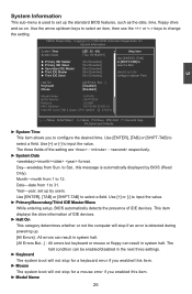
... devices. ► Halt On This category determines whether or not the computer will stop for a mouse error if you to set up the standard BIOS features, such as the date, time, floppy drive and so on. Day-weekday from 1 to input the value. ► Primary/Secondary/Third...will not stop if an error is �ab�le�d] � Mo�us� e D� isa� ble�d] Model Name :G41MD BIOS Version :A81F1D04 Memory :512MB MAC Address :90-FB-A6-30-0D-91 Intel (R) Core (TM) 2 Quad CPU Q9300 @ 2.5GHz 3 Move Enter:Select +/-/:Value...
... devices. ► Halt On This category determines whether or not the computer will stop for a mouse error if you to set up the standard BIOS features, such as the date, time, floppy drive and so on. Day-weekday from 1 to input the value. ► Primary/Secondary/Third...will not stop if an error is �ab�le�d] � Mo�us� e D� isa� ble�d] Model Name :G41MD BIOS Version :A81F1D04 Memory :512MB MAC Address :90-FB-A6-30-0D-91 Intel (R) Core (TM) 2 Quad CPU Q9300 @ 2.5GHz 3 Move Enter:Select +/-/:Value...

English Manual
Page 33
3 Model name of this information and discuss with the field service people if a BIOS upgrade is needed. ► Memory This item shows the information of the system memory, determined by POST(Power On Self Test) of the BIOS. ► MAC Address This item shows the onboard LAN MAC address. 26 User can check this product. ► BIOS Version It displays the current BIOS version.
3 Model name of this information and discuss with the field service people if a BIOS upgrade is needed. ► Memory This item shows the information of the system memory, determined by POST(Power On Self Test) of the BIOS. ► MAC Address This item shows the onboard LAN MAC address. 26 User can check this product. ► BIOS Version It displays the current BIOS version.
English Manual
Page 34
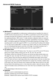
... device can conduct their transactions for MPS 1.4, you start facing problems like stuttering sound or a less responsive system, reduce the latency. Advanced BIOS Features M�P�S �Re�vis�io� n 1�.4 He�lp�Ite�m PCI Latency Timer [... Timer will reduce the effective PCI bandwidth while higher values means every PCI device will actually reduce performance as the default 1.4. Advanced BIOS Features CMOS Setup Utility - The MPS is in the future. In addition, MPS 1.4 introduces support for PCI device latency timer ...
... device can conduct their transactions for MPS 1.4, you start facing problems like stuttering sound or a less responsive system, reduce the latency. Advanced BIOS Features M�P�S �Re�vis�io� n 1�.4 He�lp�Ite�m PCI Latency Timer [... Timer will reduce the effective PCI bandwidth while higher values means every PCI device will actually reduce performance as the default 1.4. Advanced BIOS Features CMOS Setup Utility - The MPS is in the future. In addition, MPS 1.4 introduces support for PCI device latency timer ...

English Manual
Page 35
The available settings are: On (default) and Off. 28 3 ► Quick Boot While Enabled, this option allows BIOS to skip certain tests while booting, this will shorten the time needed to boot the system. ► Bootup Num-Lock This item defines if the keyboard Num Lock key is active when your system is started.
The available settings are: On (default) and Off. 28 3 ► Quick Boot While Enabled, this option allows BIOS to skip certain tests while booting, this will shorten the time needed to boot the system. ► Bootup Num-Lock This item defines if the keyboard Num Lock key is active when your system is started.

English Manual
Page 36
... [333] PCI Express Clock [100] Help Item Move Enter:Select +/-/:Value F10:Save ESC:Exit F1:General Help F9:Optimized Defaults ► Smart BIOS / CPU Configuration / Voltage Options Press to go to its submenu. ► Spread Spectrum If you can type the desired value by the system,...the desired value by using the numeric keypad. 29 When enabled, the system will turn off clock of PCI Express slot. Super BIOS Protect function protects your BIOS from virus attack, there is used to comply with FCC regulation. It may enhance the graphics card speed. 3 Fox Central Control...
... [333] PCI Express Clock [100] Help Item Move Enter:Select +/-/:Value F10:Save ESC:Exit F1:General Help F9:Optimized Defaults ► Smart BIOS / CPU Configuration / Voltage Options Press to go to its submenu. ► Spread Spectrum If you can type the desired value by the system,...the desired value by using the numeric keypad. 29 When enabled, the system will turn off clock of PCI Express slot. Super BIOS Protect function protects your BIOS from virus attack, there is used to comply with FCC regulation. It may enhance the graphics card speed. 3 Fox Central Control...
English Manual
Page 37
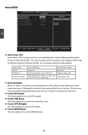
...also prevents user without password trying to get into your motherboard to enter smart boot menu. Copyright (C) 1985-2008, American Megatrends, Inc. Smart BIOS Smart Power LED Smart Boot Menu Current CPU Speed Current FSB Speed Current CPU Multiplier Current DRAM Speed [Enabled] Help Item [Enabled] : 2.... press [Del] key to enter setup or press [Esc] key to indicate different states during Power-On Self-Test (POST). Smart BIOS CMOS Setup Utility - System Status Normal No Memory Post Error Message Power LED Status Always On Continue blinking On (1sec.), Off (1sec...
...also prevents user without password trying to get into your motherboard to enter smart boot menu. Copyright (C) 1985-2008, American Megatrends, Inc. Smart BIOS Smart Power LED Smart Boot Menu Current CPU Speed Current FSB Speed Current CPU Multiplier Current DRAM Speed [Enabled] Help Item [Enabled] : 2.... press [Del] key to enter setup or press [Esc] key to indicate different states during Power-On Self-Test (POST). Smart BIOS CMOS Setup Utility - System Status Normal No Memory Post Error Message Power LED Status Always On Continue blinking On (1sec.), Off (1sec...
English Manual
Page 39
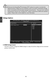
... used to dynamically adjust processor voltage and core frequency, which can result in a step of 0.2V,the voltage can be met, including CPU, chipset, motherboard, BIOS and operation system. Please refer to 0.6V. 32 Enhanced Intel SpeedStep® technology (EIST) allows the system to change the DRAM voltage in decreased average...
... used to dynamically adjust processor voltage and core frequency, which can result in a step of 0.2V,the voltage can be met, including CPU, chipset, motherboard, BIOS and operation system. Please refer to 0.6V. 32 Enhanced Intel SpeedStep® technology (EIST) allows the system to change the DRAM voltage in decreased average...
English Manual
Page 41
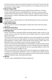
... initate graphics controller which will no longer required, it is a small EEPROM chip, mounted on system needs. DVMT allocates memory based on a memory module. This BIOS option allows you to ensure the most of the DVMT memory can send commands out to the activated memory bank. We recommend using DVMT setting...
... initate graphics controller which will no longer required, it is a small EEPROM chip, mounted on system needs. DVMT allocates memory based on a memory module. This BIOS option allows you to ensure the most of the DVMT memory can send commands out to the activated memory bank. We recommend using DVMT setting...

English Manual
Page 45
...:General Help F9:Optimized Defaults ► Serial Port1 Address This item is used to assign the I �te�m Serial Port1 Address [3F8/IRQ4] Allows BIOS to determine the transfer mode of the serial port 1. 38
...:General Help F9:Optimized Defaults ► Serial Port1 Address This item is used to assign the I �te�m Serial Port1 Address [3F8/IRQ4] Allows BIOS to determine the transfer mode of the serial port 1. 38
English Manual
Page 47
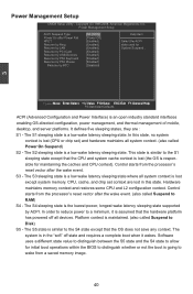
... image. 40 Software uses a different state value to distinguish between the S5 state and the S4 state to allow for initial boot operations within the BIOS to distinguish whether or not the boot is responsible for [Enabled] System Suspend . [Enabled] [Enabled] [Enabled] [Enabled] [Disabled] 3 M��o��v�e E��...
... image. 40 Software uses a different state value to distinguish between the S5 state and the S4 state to allow for initial boot operations within the BIOS to distinguish whether or not the boot is responsible for [Enabled] System Suspend . [Enabled] [Enabled] [Enabled] [Enabled] [Disabled] 3 M��o��v�e E��...


