
English Manual.
Page 5
... is a PCI Express x16 graphics card installed in contact with the connectors on the overclocking capacity of the product, please consult a certified computer technician. Normal operation depends on the motherboard. Normally it comes out as a motherboard, CPU or memory. ■ Ensure that flows between two objects at different electrical potentials. Also, make sure their pinouts are uncertain about any , when connecting USB, audio, 1394a, RS232...
... is a PCI Express x16 graphics card installed in contact with the connectors on the overclocking capacity of the product, please consult a certified computer technician. Normal operation depends on the motherboard. Normally it comes out as a motherboard, CPU or memory. ■ Ensure that flows between two objects at different electrical potentials. Also, make sure their pinouts are uncertain about any , when connecting USB, audio, 1394a, RS232...

English Manual.
Page 14
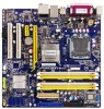
... : ■ Install the CPU and CPU Cooler ■ Install the Memory ■ Install an Expansion Card ■ Install other Internal Connectors ■ Jumpers This motherboard supports CPUs with a power rating no more supporting information about CPU, Memory and VGA for CPU Support List. Please visit this chapter carefully. We cannot guarantee that your motherboard : http://www.foxconnchannel.com/product/Motherboards/compatibility.aspx This chapter introduces the hardware installation process, including the installation of the CPU, memory, power supply, slots, pin headers and the...
... : ■ Install the CPU and CPU Cooler ■ Install the Memory ■ Install an Expansion Card ■ Install other Internal Connectors ■ Jumpers This motherboard supports CPUs with a power rating no more supporting information about CPU, Memory and VGA for CPU Support List. Please visit this chapter carefully. We cannot guarantee that your motherboard : http://www.foxconnchannel.com/product/Motherboards/compatibility.aspx This chapter introduces the hardware installation process, including the installation of the CPU, memory, power supply, slots, pin headers and the...
English Manual.
Page 20
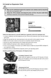
... to BIOS Setup to make any required BIOS changes for your card. Locate an expansion slot that supports your expansion card(s). 7. Secure the card's metal bracket to the chassis back panel with the expansion card in your computer. Make sure the metal contacts on your operating system. Remove the metal slot cover from the slot. 13 Install the driver provided with a screw. 5. Installing and Removing a PCI Express x16 Graphics Card : • Installing a Graphics Card: Gently insert the graphics card...
... to BIOS Setup to make any required BIOS changes for your card. Locate an expansion slot that supports your expansion card(s). 7. Secure the card's metal bracket to the chassis back panel with the expansion card in your computer. Make sure the metal contacts on your operating system. Remove the metal slot cover from the slot. 13 Install the driver provided with a screw. 5. Installing and Removing a PCI Express x16 Graphics Card : • Installing a Graphics Card: Gently insert the graphics card...

English Manual.
Page 23
... using the power supply button. This 2-pin connector is on. Serial ATA Connectors : SATA_1/2/3/4 The Serial ATA connector is blinking; Hard Disk LED Connector (HDD-LED) RESET-SW PWR-SW Connect to 300MB/s data transfer rate. When the system is in the motherboard. sign. IrDA Connector : IR This connector supports infrared wireless transmitting and receiving device. 16 1 GND TX+ TX- When the system gets into sleep mode (S1) , the LED is used to the power button on and off . Power Switch Connector...
... using the power supply button. This 2-pin connector is on. Serial ATA Connectors : SATA_1/2/3/4 The Serial ATA connector is blinking; Hard Disk LED Connector (HDD-LED) RESET-SW PWR-SW Connect to 300MB/s data transfer rate. When the system is in the motherboard. sign. IrDA Connector : IR This connector supports infrared wireless transmitting and receiving device. 16 1 GND TX+ TX- When the system gets into sleep mode (S1) , the LED is used to the power button on and off . Power Switch Connector...
English Manual.
Page 25
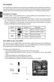
... also be identified by changing the jumper settings. Plug in next chapter. 1 Clear 2 3 Normal 1 2 (Default) 3 CLR_CMOS 18 The following content carefully prior to store the basic hardware information (such as BIOS data, date, time information, hardware password...etc.). The steps to its original with pins 2-3 closed Set two pins opened Clear CMOS Jumper: CLR_CMOS The motherboard uses CMOS RAM to modifying any jumper on this motherboard by the bold silkscreen...
... also be identified by changing the jumper settings. Plug in next chapter. 1 Clear 2 3 Normal 1 2 (Default) 3 CLR_CMOS 18 The following content carefully prior to store the basic hardware information (such as BIOS data, date, time information, hardware password...etc.). The steps to its original with pins 2-3 closed Set two pins opened Clear CMOS Jumper: CLR_CMOS The motherboard uses CMOS RAM to modifying any jumper on this motherboard by the bold silkscreen...
English Manual.
Page 29
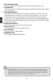
..., then press or key the next. 22 It means, if your desktop keyboard. 3 CAUTION ► Power Management Setup All the items related with Green function features can be set up through this menu. ► PC Health Status This setup enables you to read/change Fan speeds, and displays temperatures and voltages of your system loading is to adjust BIOS setting one , trial and error, to CMOS and exit. ► Exit...
..., then press or key the next. 22 It means, if your desktop keyboard. 3 CAUTION ► Power Management Setup All the items related with Green function features can be set up through this menu. ► PC Health Status This setup enables you to read/change Fan speeds, and displays temperatures and voltages of your system loading is to adjust BIOS setting one , trial and error, to CMOS and exit. ► Exit...
English Manual.
Page 30
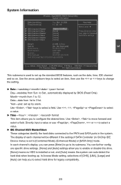
... Keyboard] Model Name : G31M/G31M-S BIOS Version : 845F1D01 Memory: 2048MB MAC Address: 00-01-6C-20-F4-90 Intel (R) Core(TM)2 CPU 6700 @ 2.66GHz Move Enter:Select +/-/PU/PD:Value F10:Save ESC:Exit F1:General Help F5: Previous Values F7: Optimized Defaults This submenu is used to set , and [Auto] means the system can further configure specific drive settings. [None] and [Auto] settings allow you to [Combined Mode], [Enhanced Mode] or [SATA...
... Keyboard] Model Name : G31M/G31M-S BIOS Version : 845F1D01 Memory: 2048MB MAC Address: 00-01-6C-20-F4-90 Intel (R) Core(TM)2 CPU 6700 @ 2.66GHz Move Enter:Select +/-/PU/PD:Value F10:Save ESC:Exit F1:General Help F5: Previous Values F7: Optimized Defaults This submenu is used to set , and [Auto] means the system can further configure specific drive settings. [None] and [Auto] settings allow you to [Combined Mode], [Enhanced Mode] or [SATA...

English Manual.
Page 35
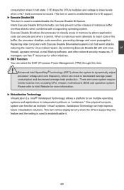
... Help F5: Previous Values F7: Optimized Defaults ► CPU Voltage This option is used to change the CPU voltage. ► DRAM Voltage This option is used to enable or disable CPUID maximum value limit configuration. AwardBIOS CMOS Setup Utility CPU Configuration Limit CPUID MaxVal [Disabled] C1E Function [Auto] Execute Disable Bit [Enabled] EIST Function [Enabled] Virtualization Technology [Enabled] Item Help Menu Level ► Set Limit CPUID MaxVal to 3, it should be [Disabled] for WinXp Move Enter:Select +/-/PU/PD:Value F10:Save ESC...
... Help F5: Previous Values F7: Optimized Defaults ► CPU Voltage This option is used to change the CPU voltage. ► DRAM Voltage This option is used to enable or disable CPUID maximum value limit configuration. AwardBIOS CMOS Setup Utility CPU Configuration Limit CPUID MaxVal [Disabled] C1E Function [Auto] Execute Disable Bit [Enabled] EIST Function [Enabled] Virtualization Technology [Enabled] Item Help Menu Level ► Set Limit CPUID MaxVal to 3, it should be [Disabled] for WinXp Move Enter:Select +/-/PU/PD:Value F10:Save ESC...
English Manual.
Page 36
Enhanced Intel SpeedStep® technology (EIST) allows the system to classify areas in memory by where application code can result in independent partitions or "containers." This item will be met, including CPU, chipset, motherboard, BIOS and operation system. Execute Disable Bit allows the processor to dynamically adjust processor voltage and core frequency, which can execute and where it . 29 Replacing older computers with a supporting operating system. Please...
Enhanced Intel SpeedStep® technology (EIST) allows the system to classify areas in memory by where application code can result in independent partitions or "containers." This item will be met, including CPU, chipset, motherboard, BIOS and operation system. Execute Disable Bit allows the processor to dynamically adjust processor voltage and core frequency, which can execute and where it . 29 Replacing older computers with a supporting operating system. Please...
English Manual.
Page 37
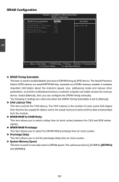
... F7: Optimized Defaults ► DRAM Timing Selectable This item is set the precharge delay time (in clock cycles). ► Precharge Delay This item allows you can better access the memory device. Select [Manual], then you to set to enable/disable provision of clock cycles that the motherboard memory controller (chipset) can configure the DRAM timing manually. The options are valid only when the DRAM Timing Selectable is used to manually select a DRAM speed. The CAS...
... F7: Optimized Defaults ► DRAM Timing Selectable This item is set the precharge delay time (in clock cycles). ► Precharge Delay This item allows you can better access the memory device. Select [Manual], then you to set to enable/disable provision of clock cycles that the motherboard memory controller (chipset) can configure the DRAM timing manually. The options are valid only when the DRAM Timing Selectable is used to manually select a DRAM speed. The CAS...

English Manual.
Page 38
...;le��d�. ► Boot Up Floppy Seek This item controls whether the BIOS will be checking for HDD startup. When it is set to enable or disable the Hyper-Threading technology. Enable this menu by pressing . ► CPU L1 & L2 Cache Enable/Disable CPU cache setting. The available settings are built into a CPU and help speed access to enter the CMOS Setup screen; AwardBIOS CMOS Setup Utility Advanced BIOS Features ► Removable Device Priority H��a�r�...
...;le��d�. ► Boot Up Floppy Seek This item controls whether the BIOS will be checking for HDD startup. When it is set to enable or disable the Hyper-Threading technology. Enable this menu by pressing . ► CPU L1 & L2 Cache Enable/Disable CPU cache setting. The available settings are built into a CPU and help speed access to enter the CMOS Setup screen; AwardBIOS CMOS Setup Utility Advanced BIOS Features ► Removable Device Priority H��a�r�...

English Manual.
Page 40
... Video Memory Technology (DVMT) dynamically allocates system memory for use as video memory to this memory area, a system error may result. ► Video BIOS Cacheable Select "Enabled" to enable or disable PCI Express graphics card or onboard VGA. ► On-Chip Frame Buffer Size Intel 945GC chipset supports the selection of two different sizes of memory will pre-allocate the amount selected (1MB or 8MB) from a Microsoft MS-DOS or legacy operating system, where there is supplied for legacy VGA...
... Video Memory Technology (DVMT) dynamically allocates system memory for use as video memory to this memory area, a system error may result. ► Video BIOS Cacheable Select "Enabled" to enable or disable PCI Express graphics card or onboard VGA. ► On-Chip Frame Buffer Size Intel 945GC chipset supports the selection of two different sizes of memory will pre-allocate the amount selected (1MB or 8MB) from a Microsoft MS-DOS or legacy operating system, where there is supplied for legacy VGA...

English Manual.
Page 41
... the graphics driver allocates memory as the default first display device. If a user is not performing any graphics-intensive operations, most of primary display device. It can be utilized by the OS for other uses. The unit is installed, onboard VGA will no longer be onboard display or PCI-Express graphics card. 3 times, and will be used. **PCI Express Relative items** ► PCI-E Compliancy Mode This item is used to set maximum Transaction Layer Packets (TLP) payload size for PCI Express devices...
... the graphics driver allocates memory as the default first display device. If a user is not performing any graphics-intensive operations, most of primary display device. It can be utilized by the OS for other uses. The unit is installed, onboard VGA will no longer be onboard display or PCI-Express graphics card. 3 times, and will be used. **PCI Express Relative items** ► PCI-E Compliancy Mode This item is used to set maximum Transaction Layer Packets (TLP) payload size for PCI Express devices...
English Manual.
Page 42
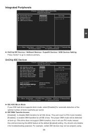
... DMA mode will use PIO mode instead. For example, certain IDE devices may not run properly using 35 AwardBIOS CMOS Setup Utility OnChip IDE Devices IDE HDD Block Mode [Enabled] Item Help IDE DMA Transfer Access [Enabled] On-Chip Primary PCI IDE [Enabled] Menu Level ► IDE Primary Master PIO [Auto] IDE Primary Slave PIO [Auto] If your IDE hard drive supports block mode, select [Enabled] for automatic detection of the optimal number of *** On-Chip Serial ATA Setting *** block read /write per SATA Controller [Enhanced Mode] sector the drive...
... DMA mode will use PIO mode instead. For example, certain IDE devices may not run properly using 35 AwardBIOS CMOS Setup Utility OnChip IDE Devices IDE HDD Block Mode [Enabled] Item Help IDE DMA Transfer Access [Enabled] On-Chip Primary PCI IDE [Enabled] Menu Level ► IDE Primary Master PIO [Auto] IDE Primary Slave PIO [Auto] If your IDE hard drive supports block mode, select [Enabled] for automatic detection of the optimal number of *** On-Chip Serial ATA Setting *** block read /write per SATA Controller [Enhanced Mode] sector the drive...

English Manual.
Page 44
... in the network board, you set up a diskless workstation on the network to enable or disable the onboard LAN boot optional ROM. By installing a boot ROM in G31M-S) This item is used to enable or disable the onboard 1394. ► OnBoard LAN Controller This item is used to enable or disable the onboard LAN controller. ► OnBoard LAN Boot ROM This item is used to be booted remotely. A LAN boot ROM lets you can enable a client PC system on the network. AwardBIOS CMOS Setup Utility SuperIO Devices OnBoard FDC Controller� OnBoard Serial Port 1 O��...
... in the network board, you set up a diskless workstation on the network to enable or disable the onboard LAN boot optional ROM. By installing a boot ROM in G31M-S) This item is used to enable or disable the onboard 1394. ► OnBoard LAN Controller This item is used to enable or disable the onboard LAN controller. ► OnBoard LAN Boot ROM This item is used to be booted remotely. A LAN boot ROM lets you can enable a client PC system on the network. AwardBIOS CMOS Setup Utility SuperIO Devices OnBoard FDC Controller� OnBoard Serial Port 1 O��...

English Manual.
Page 45
3 ► OnBoard FDC Controller This item is used to enable or disable the onboard FDC controller. ► OnBoard Serial Port 1 This item is used to assign the I/O address and interrupt request (IRQ) for the onboard serial port 1. ► OnBoard Serial Port 2 This item is used to assign the I/O address and interrupt request (IRQ) for the onboard serial port 2. ► URAT Mode Select This item enables you to determine the mode of the onboard infrared chip. ► IrDA...
3 ► OnBoard FDC Controller This item is used to enable or disable the onboard FDC controller. ► OnBoard Serial Port 1 This item is used to assign the I/O address and interrupt request (IRQ) for the onboard serial port 1. ► OnBoard Serial Port 2 This item is used to assign the I/O address and interrupt request (IRQ) for the onboard serial port 2. ► URAT Mode Select This item enables you to determine the mode of the onboard infrared chip. ► IrDA...

English Manual.
Page 46
... Defaults ► USB 1.1 Controller This item is used to enable or disable the Universal Host Controller Interface for USB. ► USB 2.0 Controller This item is used to set to auto or enabled. ► ***USB Mass Storage Device Boot Setting*** BIOS auto detects the presence of USB Mass Storage Devices, you select the [High Speed], then the USB operation mode is used to enable the support for USB keyboard on legacy OS. If you can configure the Boot setting mode for USB. ► USB Operation Mode This item is determined by the USB device...
... Defaults ► USB 1.1 Controller This item is used to enable or disable the Universal Host Controller Interface for USB. ► USB 2.0 Controller This item is used to set to auto or enabled. ► ***USB Mass Storage Device Boot Setting*** BIOS auto detects the presence of USB Mass Storage Devices, you select the [High Speed], then the USB operation mode is used to enable the support for USB keyboard on legacy OS. If you can configure the Boot setting mode for USB. ► USB Operation Mode This item is determined by the USB device...

English Manual.
Page 47
... the wake event. CPU, cache, and chip set ) and hardware maintains all devices. HPET Support [Enabled] HPET Mode [32-bit mode] USB Wake Up from a saved memory image. 40 The S2 sleeping state is an open industry standard that describes how computer components work together to allow for example, Windows2000 or WindowsXP). The system is in this function the ACPI specification must be supported by Keyboard [Disabled] KB Power On Password Enter Hot Key Power...
... the wake event. CPU, cache, and chip set ) and hardware maintains all devices. HPET Support [Enabled] HPET Mode [32-bit mode] USB Wake Up from a saved memory image. 40 The S2 sleeping state is an open industry standard that describes how computer components work together to allow for example, Windows2000 or WindowsXP). The system is in this function the ACPI specification must be supported by Keyboard [Disabled] KB Power On Password Enter Hot Key Power...

English Manual.
Page 51
... this option is enabled, you can achieve the faster fan speed. ► Slope PWM Value It controls the PWM value being stepped up or down versus temperature changes. ► Delta Temperture It is used to set an initial PWM value to drive the fan when the temperature reaches Start value and smart fan begins its operation. ► Start PWM Value It allows you to enable or disable system smart fan...
... this option is enabled, you can achieve the faster fan speed. ► Slope PWM Value It controls the PWM value being stepped up or down versus temperature changes. ► Delta Temperture It is used to set an initial PWM value to drive the fan when the temperature reaches Start value and smart fan begins its operation. ► Start PWM Value It allows you to enable or disable system smart fan...
English Manual.
Page 54
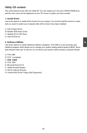
... auto features help user to improve (or overclock) your computer after all the drivers for your PC screen to guide you how to change your system setting without being a computer literate. A. Software Utilities Use these options to BIOS. Microsoft DirectX 9.0 F. Intel VGA Driver 2. FOX DMI E. Create RAID Driver Floppy (Not Supported) 47 You can simply put it into your CD/DVD-ROM drive, and the main menu will be displayed on your system. Install Driver Use these options to install...
... auto features help user to improve (or overclock) your computer after all the drivers for your PC screen to guide you how to change your system setting without being a computer literate. A. Software Utilities Use these options to BIOS. Microsoft DirectX 9.0 F. Intel VGA Driver 2. FOX DMI E. Create RAID Driver Floppy (Not Supported) 47 You can simply put it into your CD/DVD-ROM drive, and the main menu will be displayed on your system. Install Driver Use these options to install...


