English Manual.
Page 6
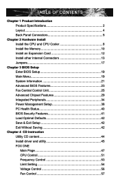
... Introduction Product Specifications 2 Layout 4 Back Panel Connectors 5 Chapter 2 Hardware Install Install the CPU and CPU Cooler 8 Install the Memory 10 Install an Expansion Card 12 Install other Internal Connectors 13 Jumpers 17 Chapter 3 BIOS Setup Enter BIOS Setup 19 Main Menu 19 System Information 21 Advanced BIOS Features 23 Fox Central Control Unit 25 Advanced Chipset Features 29 Integrated Peripherals 34 Power Management Setup 38 PC Health Status 40 BIOS Security Features 41 Load Optimal Defaults 42 Save & Exit Setup 42 Exit...
... Introduction Product Specifications 2 Layout 4 Back Panel Connectors 5 Chapter 2 Hardware Install Install the CPU and CPU Cooler 8 Install the Memory 10 Install an Expansion Card 12 Install other Internal Connectors 13 Jumpers 17 Chapter 3 BIOS Setup Enter BIOS Setup 19 Main Menu 19 System Information 21 Advanced BIOS Features 23 Fox Central Control Unit 25 Advanced Chipset Features 29 Integrated Peripherals 34 Power Management Setup 38 PC Health Status 40 BIOS Security Features 41 Load Optimal Defaults 42 Save & Exit Setup 42 Exit...
English Manual.
Page 7
... DMI 67 Chapter 5 RAID Configuration RAID Configuration Introduction 70 Option ROM Utility 72 Create a RAID Driver Diskette 74 RAID Enable in BIOS 76 Select a RAID Array for Use 76 Install a New Windows XP 89 Setting Up a Non-Bootable RAID Array 93 Technical Support : Website : http://www.foxconnchannel.com Support Support Website : http://www.foxconnsupport.com Worldwide online contact Support : http://www.foxconnchannel.com/support/online.aspx CPU, Memory, VGA Compatibility Supporting Website : http://www.foxconnchannel.com/product/Motherboards/compatibility.aspx
... DMI 67 Chapter 5 RAID Configuration RAID Configuration Introduction 70 Option ROM Utility 72 Create a RAID Driver Diskette 74 RAID Enable in BIOS 76 Select a RAID Array for Use 76 Install a New Windows XP 89 Setting Up a Non-Bootable RAID Array 93 Technical Support : Website : http://www.foxconnchannel.com Support Support Website : http://www.foxconnsupport.com Worldwide online contact Support : http://www.foxconnchannel.com/support/online.aspx CPU, Memory, VGA Compatibility Supporting Website : http://www.foxconnchannel.com/product/Motherboards/compatibility.aspx
English Manual.
Page 10
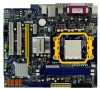
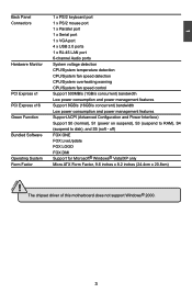
.../2 keyboard port Connectors 1 x PS/2 mouse port 1 x Parallel port 1 x Serial port 1 x VGA port 4 x USB 2.0 ports 1 x RJ-45 LAN port 6-channel Audio ports Hardware Monitor System voltage detection CPU/System temperature detection CPU/System fan speed detection CPU/System overheating warning CPU/System fan speed control PCI Express x1 Support 500MB/s (1GB/s concurrent) bandwidth Low power consumption and power management features PCI Express x16 Support 8GB/s (16GB/s concurrent) bandwidth Low power consumption and power management features Green Function Support ACPI...
.../2 keyboard port Connectors 1 x PS/2 mouse port 1 x Parallel port 1 x Serial port 1 x VGA port 4 x USB 2.0 ports 1 x RJ-45 LAN port 6-channel Audio ports Hardware Monitor System voltage detection CPU/System temperature detection CPU/System fan speed detection CPU/System overheating warning CPU/System fan speed control PCI Express x1 Support 500MB/s (1GB/s concurrent) bandwidth Low power consumption and power management features PCI Express x16 Support 8GB/s (16GB/s concurrent) bandwidth Low power consumption and power management features Green Function Support ACPI...
English Manual.
Page 12
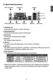
...In 5.1-channel Rear Speaker Out* Front Speaker Out Center/Subwoofer Out* * : Please refer to assign the audio output ports for USB devices such as monitor or LCD display. 6. VGA Port To connect with external display devices, such as an USB keyboard/mouse, USB printer, USB flash drive and etc. 7. 1 1-3 Back Panel Connectors PS/2 Mouse Port 1 Parallel Port 3 LAN Port 8 Line In Line Out Microphone 2 4 5 PS/2 Keyboard Port Serial Port VGA Port 6 USB Ports 7 Audio Ports 1. PS/2 Keyboard Port Use the lower port (purple) to connect a PS/2 mouse. 2. USB Ports The USB port...
...In 5.1-channel Rear Speaker Out* Front Speaker Out Center/Subwoofer Out* * : Please refer to assign the audio output ports for USB devices such as monitor or LCD display. 6. VGA Port To connect with external display devices, such as an USB keyboard/mouse, USB printer, USB flash drive and etc. 7. 1 1-3 Back Panel Connectors PS/2 Mouse Port 1 Parallel Port 3 LAN Port 8 Line In Line Out Microphone 2 4 5 PS/2 Keyboard Port Serial Port VGA Port 6 USB Ports 7 Audio Ports 1. PS/2 Keyboard Port Use the lower port (purple) to connect a PS/2 mouse. 2. USB Ports The USB port...
English Manual.
Page 19
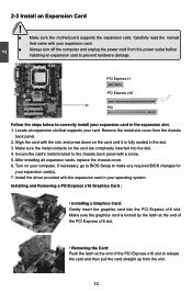
... the motherboard supports the expansion card. Locate an expansion slot that came with the expansion card in your computer. After installing all expansion cards, replace the chassis cover. 6. Installing and Removing a PCI Express x16 Graphics Card : • Installing a Graphics Card: Gently insert the graphics card into the slot. 4. Make sure the metal contacts on the card are completely inserted into the PCI Express x16 slot. If necessary, go to BIOS Setup to correctly install your expansion card. ■ Always turn off...
... the motherboard supports the expansion card. Locate an expansion slot that came with the expansion card in your computer. After installing all expansion cards, replace the chassis cover. 6. Installing and Removing a PCI Express x16 Graphics Card : • Installing a Graphics Card: Gently insert the graphics card into the slot. 4. Make sure the metal contacts on the card are completely inserted into the PCI Express x16 slot. If necessary, go to BIOS Setup to correctly install your expansion card. ■ Always turn off...
English Manual.
Page 21
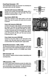
... 2-pin connector is directional with SATA Hard Disk or CD devices which supporting this feature. Push this function, you should purchase additional device and install it. 14 1 + HDD-LED - 2 + PWR-LED - sign. When the system is in operation (S0 status), the LED is used to the power LED indicator on the front panel of the hard disks. It indicates the active status of the chassis. When the system gets into sleep mode...
... 2-pin connector is directional with SATA Hard Disk or CD devices which supporting this feature. Push this function, you should purchase additional device and install it. 14 1 + HDD-LED - 2 + PWR-LED - sign. When the system is in operation (S0 status), the LED is used to the power LED indicator on the front panel of the hard disks. It indicates the active status of the chassis. When the system gets into sleep mode...
English Manual.
Page 24
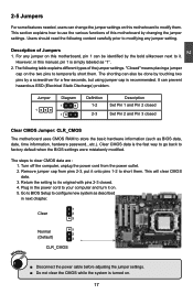
... a few seconds, but using jumper cap is simply labeled as BIOS data, date, time information, hardware password...etc.). The steps to temporarily short them. Go to BIOS Setup to store the basic hardware information (such as "1". 2. Description of the jumper settings. Remove jumper cap from the power outlet. 2. Return the setting to its original with pins 2-3 closed Clear CMOS Jumper: CLR_CMOS The motherboard uses CMOS RAM to configure new system as described...
... a few seconds, but using jumper cap is simply labeled as BIOS data, date, time information, hardware password...etc.). The steps to temporarily short them. Go to BIOS Setup to store the basic hardware information (such as "1". 2. Description of the jumper settings. Remove jumper cap from the power outlet. 2. Return the setting to its original with pins 2-3 closed Clear CMOS Jumper: CLR_CMOS The motherboard uses CMOS RAM to configure new system as described...
English Manual.
Page 28
CMOS Setup Utility - Floppy A Halt On Keyboard Mouse Floppy [1.44 MB 31/2] [All Errors, But ...] [Enabled] [Enabled] [Disabled] Model Name BIOS Version Memory MAC Address : A7VML/A76ML Series :D07 :256M :00-E0-4C-36-00-02 Move Enter:Select +/-/:Value F10:Save ESC:Exit F1:General Help F9:Optimized Defaults 3 ► Date (mm:dd:yy) format. The 21 Month-month from 1 to configure the desired time. Year-year, set up /down...
CMOS Setup Utility - Floppy A Halt On Keyboard Mouse Floppy [1.44 MB 31/2] [All Errors, But ...] [Enabled] [Enabled] [Disabled] Model Name BIOS Version Memory MAC Address : A7VML/A76ML Series :D07 :256M :00-E0-4C-36-00-02 Move Enter:Select +/-/:Value F10:Save ESC:Exit F1:General Help F9:Optimized Defaults 3 ► Date (mm:dd:yy) format. The 21 Month-month from 1 to configure the desired time. Year-year, set up /down...
English Manual.
Page 29
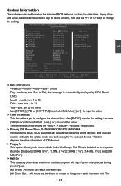
...; BIOS Version It displays the current BIOS version. User can be enabled/disabled in your system before powering on how many memory modules were installed in the next three settings. ► Keyboard The system boot will not stop for a keyboard error if you enabled this item. ► Mouse The system boot will not stop for a mouse error if you enabled this item. ► Floppy The system boot will not stop for a floppy error if...
...; BIOS Version It displays the current BIOS version. User can be enabled/disabled in your system before powering on how many memory modules were installed in the next three settings. ► Keyboard The system boot will not stop for a keyboard error if you enabled this item. ► Mouse The system boot will not stop for a mouse error if you enabled this item. ► Floppy The system boot will not stop for a floppy error if...

English Manual.
Page 30
... another takes over the set . Advanced BIOS Features IDE Detect Time Out MPS Revision PCI Latency Timer Quiet Boot Quick Boot Bootup Num-Lock Floppy Drive Seek ► Boot Device Priority ► Hard Disk Drives ► Removable Drives ► CD/DVD Drives [35] Help Item [1.4] [64] Select the time out [Enabled] value for detecting [Enabled] ATA/ATAPI device(s) [On] in second . [Disabled] [Press Enter] [Press Enter] [Press Enter] [Press Enter] 3 Move Enter:Select +/-/:Value F10:Save...
... another takes over the set . Advanced BIOS Features IDE Detect Time Out MPS Revision PCI Latency Timer Quiet Boot Quick Boot Bootup Num-Lock Floppy Drive Seek ► Boot Device Priority ► Hard Disk Drives ► Removable Drives ► CD/DVD Drives [35] Help Item [1.4] [64] Select the time out [Enabled] value for detecting [Enabled] ATA/ATAPI device(s) [On] in second . [Disabled] [Press Enter] [Press Enter] [Press Enter] [Press Enter] 3 Move Enter:Select +/-/:Value F10:Save...
English Manual.
Page 32
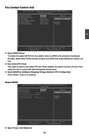
... go to auto detect PCI slot. Smart BIOS Smart Power LED [Disabled] Help Item Smart Boot Menu Current CPU Speed [Enabled] : 2400MHz Options Current FSB/HTT Speed : 200MHz Current FSB Multiplier : 12x Disabled Current DRAM Speed : 533 MHz, N/A Enabled Move Enter:Select F1:General Help ► Smart Power LED (Optional) +/-/:Value F10:Save ESC:Exit F9:Optimized Defaults 25 Smart BIOS CMOS Setup Utility - Copyright (C) 1985-2008, American Megatrends, Inc. Super BIOS Protect function protects your BIOS from virus attack, there is used to its...
... go to auto detect PCI slot. Smart BIOS Smart Power LED [Disabled] Help Item Smart Boot Menu Current CPU Speed [Enabled] : 2400MHz Options Current FSB/HTT Speed : 200MHz Current FSB Multiplier : 12x Disabled Current DRAM Speed : 533 MHz, N/A Enabled Move Enter:Select F1:General Help ► Smart Power LED (Optional) +/-/:Value F10:Save ESC:Exit F9:Optimized Defaults 25 Smart BIOS CMOS Setup Utility - Copyright (C) 1985-2008, American Megatrends, Inc. Super BIOS Protect function protects your BIOS from virus attack, there is used to its...

English Manual.
Page 39
...) or performance. PCIe graphics card is the ATI technology that provides multi-graphics controller display capability for use as video memory to select which graphics controller is used to ensure the most efficient use . 2. CMOS Setup Utility - This item allows you to select a delay time (in the BIOS 32 Copyright (C) 1985-2008, American Megatrends, Inc. Help Item Internal Graphics Mode UMA Frame Buffer Size Primary Video Controller Surround View [Enabled] Options [128MB] [PCI-GFXO-IGFX] Disabled [Disabled] Enabled 3 Move Enter:Select...
...) or performance. PCIe graphics card is the ATI technology that provides multi-graphics controller display capability for use as video memory to select which graphics controller is used to ensure the most efficient use . 2. CMOS Setup Utility - This item allows you to select a delay time (in the BIOS 32 Copyright (C) 1985-2008, American Megatrends, Inc. Help Item Internal Graphics Mode UMA Frame Buffer Size Primary Video Controller Surround View [Enabled] Options [128MB] [PCI-GFXO-IGFX] Disabled [Disabled] Enabled 3 Move Enter:Select...
English Manual.
Page 41
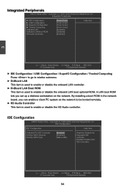
... the network. By installing a boot ROM in the network board, you set up a diskless workstation on the network to be booted remotely. ► HD Audio Controller This item is used to enable or disable the onboard LAN boot optional ROM. Enabled: Enable both IDE controllers. IDE Configuration CMOS Setup Utility - IDE Configuration IDE Configuration Help Item OnBoard PCI IDE Controller [Enabled] Disabled: Disable the OnChip SATA Channel [Enabled] I integrated IDE OnChip SATA Type...
... the network. By installing a boot ROM in the network board, you set up a diskless workstation on the network to be booted remotely. ► HD Audio Controller This item is used to enable or disable the onboard LAN boot optional ROM. Enabled: Enable both IDE controllers. IDE Configuration CMOS Setup Utility - IDE Configuration IDE Configuration Help Item OnBoard PCI IDE Controller [Enabled] Disabled: Disable the OnChip SATA Channel [Enabled] I integrated IDE OnChip SATA Type...
English Manual.
Page 42
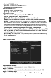
... (AHCI) specification describes the register level interface for a Host Controller for old Windows system. USB Configuration USB Configuration Help Item USB Devices Enabled : Options 1 Drive Disabled OnBoard USB Controller [Enabled] Enabled USB 2.0 Controller [Enabled] USB 2.0 Controller Mode [High Speed] Legacy USB Support [Enabled] ► USB Storage Configuration [Press Enter Move Enter:Select +/-/:Value F10:Save ESC:Exit F1:General Help F9:Optimized Defaults ► OnBoard USB Controller This item is used to enable...
... (AHCI) specification describes the register level interface for a Host Controller for old Windows system. USB Configuration USB Configuration Help Item USB Devices Enabled : Options 1 Drive Disabled OnBoard USB Controller [Enabled] Enabled USB 2.0 Controller [Enabled] USB 2.0 Controller Mode [High Speed] Legacy USB Support [Enabled] ► USB Storage Configuration [Press Enter Move Enter:Select +/-/:Value F10:Save ESC:Exit F1:General Help F9:Optimized Defaults ► OnBoard USB Controller This item is used to enable...
English Manual.
Page 45
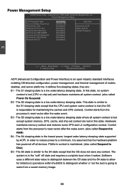
... context is lost except system memory. Software uses a different state value to distinguish between the S5 state and the S4 state to wake from a saved memory image. 38 In this state. CPU, cache, and chip set ) and hardware maintains all devices. Power Management Setup CMOS Setup Utility - Control starts from the processor's reset vector after the wake event. Control starts from the processor's reset vector after the wake event. (also called Power On Suspend) S2 -
... context is lost except system memory. Software uses a different state value to distinguish between the S5 state and the S4 state to wake from a saved memory image. 38 In this state. CPU, cache, and chip set ) and hardware maintains all devices. Power Management Setup CMOS Setup Utility - Control starts from the processor's reset vector after the wake event. Control starts from the processor's reset vector after the wake event. (also called Power On Suspend) S2 -
English Manual.
Page 51
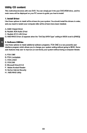
... you to change your system setting without being a computer literate. 4 Utility CD content This motherboard comes with one DVD. AMD Chipset Driver B. FOX DMI E. Realtek 811X LAN Driver D. AMD RAID Utility 44 A. FOX ONE B. Norton Internet Security H. You can simply put it into your DVD-ROM drive, and the main menu will be displayed on your PC screen to guide you need to improve (or overclock) your system. Some auto features help user to...
... you to change your system setting without being a computer literate. 4 Utility CD content This motherboard comes with one DVD. AMD Chipset Driver B. FOX DMI E. Realtek 811X LAN Driver D. AMD RAID Utility 44 A. FOX ONE B. Norton Internet Security H. You can simply put it into your DVD-ROM drive, and the main menu will be displayed on your PC screen to guide you need to improve (or overclock) your system. Some auto features help user to...
English Manual.
Page 76
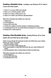
... create RAID driver diskette if it includes : 1. Use Administrative Tools in Control Panel to set RAID enabled in a brand new RAID system. 1. A motherboard driver CD. 69 Creating a Non-Bootable Array - What kinds of hardware and software you need here : 1. Follow 5-2 to format new RAID array. A RAID driver diskette. (Could be bundled in BIOS. 2. Windows XP or Vista Install CD. Run setup program to select a RAID array for use . 4. A DVD-ROM drive. 2. A DVD-ROM drive. 3. Follow 5-3 to install AMD RAID driver into...
... create RAID driver diskette if it includes : 1. Use Administrative Tools in Control Panel to set RAID enabled in a brand new RAID system. 1. A motherboard driver CD. 69 Creating a Non-Bootable Array - What kinds of hardware and software you need here : 1. Follow 5-2 to format new RAID array. A RAID driver diskette. (Could be bundled in BIOS. 2. Windows XP or Vista Install CD. Run setup program to select a RAID array for use . 4. A DVD-ROM drive. 2. A DVD-ROM drive. 3. Follow 5-3 to install AMD RAID driver into...

English Manual.
Page 83
... menu of Option ROM Utility. CMOS Setup Utility - Copyright (C) 1985-2008, American Megatrends, Inc. Press [Ctrl-F], the Main Menu appears. IDE Configuration IDE Configuration Help Item OnBoard PCI IDE Controller [Enabled] Options OnChip SATA Channel [Enabled] I OnChip SATA Type [RAID] Native IDE RAID AHCI Legacy IDE 5 Move Enter:Select +/-/:Value F10:Save ESC:Exit F1:General Help F9:Optimized Defaults 5-3 Select a RAID Array for hard drive or DVD connection. 4. Enter the BIOS setup by pressing key when boot...
... menu of Option ROM Utility. CMOS Setup Utility - Copyright (C) 1985-2008, American Megatrends, Inc. Press [Ctrl-F], the Main Menu appears. IDE Configuration IDE Configuration Help Item OnBoard PCI IDE Controller [Enabled] Options OnChip SATA Channel [Enabled] I OnChip SATA Type [RAID] Native IDE RAID AHCI Legacy IDE 5 Move Enter:Select +/-/:Value F10:Save ESC:Exit F1:General Help F9:Optimized Defaults 5-3 Select a RAID Array for hard drive or DVD connection. 4. Enter the BIOS setup by pressing key when boot...
English Manual.
Page 97
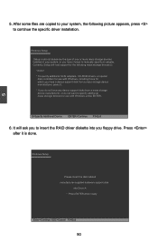
... Windows Setup Please insert the disk labeled manufacturer-supplied hardware support disk into you have any device support disks from a mass storage device manufacturer, or do not have chosen to continue the specific driver installation. It will load support for use with Windows, press ENTER. Windows Setup Setup could not determine the type of one or more mass storage devices installed in your system, the following mass storage device(s): * To specify additional SCSI adapters, CD-ROM drivers, or special disk controllers for use...
... Windows Setup Please insert the disk labeled manufacturer-supplied hardware support disk into you have any device support disks from a mass storage device manufacturer, or do not have chosen to continue the specific driver installation. It will load support for use with Windows, press ENTER. Windows Setup Setup could not determine the type of one or more mass storage devices installed in your system, the following mass storage device(s): * To specify additional SCSI adapters, CD-ROM drivers, or special disk controllers for use...
English Manual.
Page 100
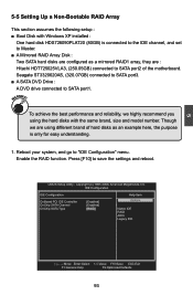
...IDE Configuration Help Item OnBoard PCI IDE Controller [Enabled] Options OnChip SATA Channel [Enabled] I OnChip SATA Type [RAID] Native IDE RAID AHCI Legacy IDE Move Enter:Select +/-/:Value F10:Save ESC:Exit F1:General Help F9:Optimized Defaults 93 5 5-5 Setting Up a Non-Bootable RAID Array This section assumes the following setup : ■ Boot Disk with the same brand, size and model number. Though we highly recommend you using different brand of hard disks as an example here, the purpose is connected to the IDE...
...IDE Configuration Help Item OnBoard PCI IDE Controller [Enabled] Options OnChip SATA Channel [Enabled] I OnChip SATA Type [RAID] Native IDE RAID AHCI Legacy IDE Move Enter:Select +/-/:Value F10:Save ESC:Exit F1:General Help F9:Optimized Defaults 93 5 5-5 Setting Up a Non-Bootable RAID Array This section assumes the following setup : ■ Boot Disk with the same brand, size and model number. Though we highly recommend you using different brand of hard disks as an example here, the purpose is connected to the IDE...


