
User Manual
Page 3
... 1.4. Gap Adjustment 18 OPERATION...20 1. Self-Test ...21 3. Operation site...4 1.5. Cartridge Ribbon Installation 15 6. LF/FF Functions ...20 2. Paper empty...23 4.3. 4K memory full 5. Contents of DIP swtiches and jumpers 9 3.1. SW-A and SW-B 9 3.3. Theory of the MX-85 Component 7 3. Construction and Location of Operation 22 4.1. Repacking ...2 1.3. Assembly ...4 1.6. Location of shipping screws 5 1.8. Setting DIP switches - Removal of DIP switches and Jumpers 9 3.2. Setting of jumpers 12 4. On-Line Operation 21 4. Low paper...22 4.2. Power Supply...
... 1.4. Gap Adjustment 18 OPERATION...20 1. Self-Test ...21 3. Operation site...4 1.5. Cartridge Ribbon Installation 15 6. LF/FF Functions ...20 2. Paper empty...23 4.3. 4K memory full 5. Contents of DIP swtiches and jumpers 9 3.1. SW-A and SW-B 9 3.3. Theory of the MX-85 Component 7 3. Construction and Location of Operation 22 4.1. Repacking ...2 1.3. Assembly ...4 1.6. Location of shipping screws 5 1.8. Setting DIP switches - Removal of DIP switches and Jumpers 9 3.2. Setting of jumpers 12 4. On-Line Operation 21 4. Low paper...22 4.2. Power Supply...

User Manual
Page 4
.... 1 MX-85 Dot Matrix Printer 1 Fig. 2 Contents of Carton 3 Fig. 3 Removal of Printer Cover 4 Fig. 4 Removal of Shipping Screws 5 Fig. 5 Removing Manual Paper Feed Knob 6 Fig. 6 Loosening All 4 Screws 6 Fig. 7 Removing Wires Connected to Control Panel 7 Fig. 8 Construction of the Printer 8 Fig. 9 Location of DIP Switches 9 Fig. 10 Setting DIP Switches 10 Fig. 11 Jumpers on the SMCT Board 13 Fig. 12 Setting of Power Supply Voltage 14 Fig. 13 Cartridge Ribbon Setting 15...
.... 1 MX-85 Dot Matrix Printer 1 Fig. 2 Contents of Carton 3 Fig. 3 Removal of Printer Cover 4 Fig. 4 Removal of Shipping Screws 5 Fig. 5 Removing Manual Paper Feed Knob 6 Fig. 6 Loosening All 4 Screws 6 Fig. 7 Removing Wires Connected to Control Panel 7 Fig. 8 Construction of the Printer 8 Fig. 9 Location of DIP Switches 9 Fig. 10 Setting DIP Switches 10 Fig. 11 Jumpers on the SMCT Board 13 Fig. 12 Setting of Power Supply Voltage 14 Fig. 13 Cartridge Ribbon Setting 15...
User Manual
Page 6
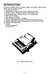
... - Operator replaceable ribbon cartridge with 100x106 character life 9. Print Speed: 80 CPS 2. High density print quality - 9x7 Matrix 8. Microprocessor controlled, logic seeking, bidirectional printing 3. High quality and reliability 7. Transmission Code: ASCII and Baudot - 45.5 to 80 mA Current Loop 4. Black 10. RS-232C and 20 to 9600 baud 5. Options: (1) Roll Paper Rewind (2) Tractor Feed Fig. 1 MX-85 Dot Matrix Printer -1- INTRODUCTION The MX-85 Dot Matrix Printer...
... - Operator replaceable ribbon cartridge with 100x106 character life 9. Print Speed: 80 CPS 2. High density print quality - 9x7 Matrix 8. Microprocessor controlled, logic seeking, bidirectional printing 3. High quality and reliability 7. Transmission Code: ASCII and Baudot - 45.5 to 80 mA Current Loop 4. Black 10. RS-232C and 20 to 9600 baud 5. Options: (1) Roll Paper Rewind (2) Tractor Feed Fig. 1 MX-85 Dot Matrix Printer -1- INTRODUCTION The MX-85 Dot Matrix Printer...

User Manual
Page 7
... protective sheet for evidence of MX-85 Before removing the MX-85 from the carton, check the box for paper sensor are reinstalled. Unpacking (1) Open carton. (2) Remove accessories; It is present, notify the carrier immediately. 1.1. ribbon, manual, etc. (3) Grasp the MX-85 by, its underside and lift straight out with 'packing material attached. (4) Place the printer on a flat surface. (5) Carefully remove packing material. (6) Remove the vinyl cover. 1.2. INSTALLATION 1.
... protective sheet for evidence of MX-85 Before removing the MX-85 from the carton, check the box for paper sensor are reinstalled. Unpacking (1) Open carton. (2) Remove accessories; It is present, notify the carrier immediately. 1.1. ribbon, manual, etc. (3) Grasp the MX-85 by, its underside and lift straight out with 'packing material attached. (4) Place the printer on a flat surface. (5) Carefully remove packing material. (6) Remove the vinyl cover. 1.2. INSTALLATION 1.

User Manual
Page 8
MX-85 Printer 2. Cartridge Ribbon 3. Filter Circuit Board If there is any evidence of Carton -3- Filter Circuit Board (Y4252O400000) 3. Operation Manual 4. Operation Manual 4. AC Power Cord 6. MX-85 Dot Matrix Pritner 5. Roll Paper Holder 1. Roll Paper Holder 5. AC Power Cord Fig. 2 Contents of damage or missing items, contact the vendor from whom the printer was purchased to report the details. 6. 1.3. Contents of carton The Carton should contain the following: 1.
MX-85 Printer 2. Cartridge Ribbon 3. Filter Circuit Board If there is any evidence of Carton -3- Filter Circuit Board (Y4252O400000) 3. Operation Manual 4. Operation Manual 4. AC Power Cord 6. MX-85 Dot Matrix Pritner 5. Roll Paper Holder 1. Roll Paper Holder 5. AC Power Cord Fig. 2 Contents of damage or missing items, contact the vendor from whom the printer was purchased to report the details. 6. 1.3. Contents of carton The Carton should contain the following: 1.
User Manual
Page 9
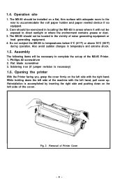
.... 3. The MX-85 should be exposed to complete the set-up . Also avoid sudden changes in temperature and extreme shock. 1.5. 1.4. Do not subject the MX-85 to accommodate the roll paper holder and paper rewind device if so equipped. 2. Flat blade screwdriver 3. Reinstallation is necessary) 1.6. Operation site 1. Assembly The following items will not be installed on the left side of Printer Cover -4- While...
.... 3. The MX-85 should be exposed to complete the set-up . Also avoid sudden changes in temperature and extreme shock. 1.5. 1.4. Do not subject the MX-85 to accommodate the roll paper holder and paper rewind device if so equipped. 2. Flat blade screwdriver 3. Reinstallation is necessary) 1.6. Operation site 1. Assembly The following items will not be installed on the left side of Printer Cover -4- While...

User Manual
Page 10
... during reshipment of the MX-85. They are necessary to prevent damage to the print mechanism which may be retained for use during transportation. Right Side of the Printer Lower Case Shipping Screws Fig. 4 Removal of shipping screws 1. Also, adequately discharge any electronic components. 1. Removal of the upper case In order to check, or change, settings of the printer by pulling up...
... during reshipment of the MX-85. They are necessary to prevent damage to the print mechanism which may be retained for use during transportation. Right Side of the Printer Lower Case Shipping Screws Fig. 4 Removal of shipping screws 1. Also, adequately discharge any electronic components. 1. Removal of the upper case In order to check, or change, settings of the printer by pulling up...

User Manual
Page 11
.... 5 Removing Manual Paper Feed Knob 3. Phillips Head #2 Screwdriver Fig. 6 Loosening All 4 Screws -6- When the case is inverted. 5. Set the cover safely aside. NOTE: Placing tape over the holes will prevent accidental loss of the screws when the Printer is partially raised, reach in the extreme corners of the bottom cover. Loosen the four (4) Phillips head screws located in and pull control panel cable loose. Turn...
.... 5 Removing Manual Paper Feed Knob 3. Phillips Head #2 Screwdriver Fig. 6 Loosening All 4 Screws -6- When the case is inverted. 5. Set the cover safely aside. NOTE: Placing tape over the holes will prevent accidental loss of the screws when the Printer is partially raised, reach in the extreme corners of the bottom cover. Loosen the four (4) Phillips head screws located in and pull control panel cable loose. Turn...

User Manual
Page 14
... the factory-set aside for code selection, word size, parity control and line feed control. They are two (2) DIP (Dual In-Line Pin) switches located on the SMDP Board and sixteen (16) jumpers located on the SMCT Board. 3.2. Be sure power is off . 3. Setting DIP switches - Remove them and set conditions of any switch. 1) Switch B, the four (4) position switch, is used only to the right are "OFF". 2. Setting of DIP Switches -9- The switches set to...
... the factory-set aside for code selection, word size, parity control and line feed control. They are two (2) DIP (Dual In-Line Pin) switches located on the SMDP Board and sixteen (16) jumpers located on the SMCT Board. 3.2. Be sure power is off . 3. Setting DIP switches - Remove them and set conditions of any switch. 1) Switch B, the four (4) position switch, is used only to the right are "OFF". 2. Setting of DIP Switches -9- The switches set to...

User Manual
Page 17
... screws located in the heat sink on the right side of the SMCT Board. Jumper J1 J2 J3 J4 J5 J6 J7 J8 J9 J10 J11 J12 J13 J14 J15 J16 Table 6 Function and Conditions of Jumpers Not used ON RS-232C OFF Level Function OFF Current Loop ON Level Note...2 20 mA Current Loop Factory-set condition of each jumper. Setting of jumpers Your application may require the removal or installation of jumpers of the board. 3. Do not connect both. Do not connect 2 or more. - 12- 3.3. This is necessary to avoid damage. NOTE: Any changes in the connector area, to remove the SMDP Board. Note ...
... screws located in the heat sink on the right side of the SMCT Board. Jumper J1 J2 J3 J4 J5 J6 J7 J8 J9 J10 J11 J12 J13 J14 J15 J16 Table 6 Function and Conditions of Jumpers Not used ON RS-232C OFF Level Function OFF Current Loop ON Level Note...2 20 mA Current Loop Factory-set condition of each jumper. Setting of jumpers Your application may require the removal or installation of jumpers of the board. 3. Do not connect both. Do not connect 2 or more. - 12- 3.3. This is necessary to avoid damage. NOTE: Any changes in the connector area, to remove the SMDP Board. Note ...

User Manual
Page 20
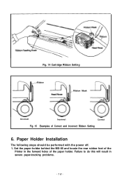
... the Printer cover. 3. Wind the ribbon counterclockwise and verify correct positioning. Remove the ribbon from its box and turn the knob counterclockwise to firmly seat it. 7. 5. Fig. 13 Cartridge Ribbon Setting -15- Guide the four (4) tabs on both ends of the head and the ribbon guide. 8. Cartridge Ribbon Installation 1. Position the Printer with the logo facing you. 2. Be sure the print scale is...
... the Printer cover. 3. Wind the ribbon counterclockwise and verify correct positioning. Remove the ribbon from its box and turn the knob counterclockwise to firmly seat it. 7. 5. Fig. 13 Cartridge Ribbon Setting -15- Guide the four (4) tabs on both ends of the head and the ribbon guide. 8. Cartridge Ribbon Installation 1. Position the Printer with the logo facing you. 2. Be sure the print scale is...
User Manual
Page 21
Paper Holder Installation The following steps should be performed with the power off. 1. Fig. 14 Cartridge Ribbon Setting -Ribbon Ribbon Mask Incorrect Incorrect Correct Fig. 15 Examples of the Printer in severe paper-tracking problems. -16- Failure to do this will result in the forward holes of the paper holder. Set the paper holder behind the MX-85 and locate the rear rubber feet of Correct and Incorrect Ribbon Setting 6.
Paper Holder Installation The following steps should be performed with the power off. 1. Fig. 14 Cartridge Ribbon Setting -Ribbon Ribbon Mask Incorrect Incorrect Correct Fig. 15 Examples of the Printer in severe paper-tracking problems. -16- Failure to do this will result in the forward holes of the paper holder. Set the paper holder behind the MX-85 and locate the rear rubber feet of Correct and Incorrect Ribbon Setting 6.

User Manual
Page 22
... connected to the "Low Paper" sensor, into the mating connector located alongside of the 25-pin EIA connector on the right side of the printer to approximately the center of the platen on the print scale to retain the paper firmly. 10. Position the plastic tubes on the MX-85. 7. Pull the paper release forward and align the paper. 9. Close the printer cover. Lift the printer cover...
... connected to the "Low Paper" sensor, into the mating connector located alongside of the 25-pin EIA connector on the right side of the printer to approximately the center of the platen on the print scale to retain the paper firmly. 10. Position the plastic tubes on the MX-85. 7. Pull the paper release forward and align the paper. 9. Close the printer cover. Lift the printer cover...

User Manual
Page 25
... Line Feed (LF) button. Turn on the control panel. LF/FF Functions 1. NOTE: Both of these switches will return to the left side of the Printer. 1) Buzzer will sound. 2) Print head will function while On-line. This is being received, printing will be interrupted and the LF or FF function will be performed. OPERATION Power On 1. switch located to the rear on the right side of the Printer. 3) The "Power...
... Line Feed (LF) button. Turn on the control panel. LF/FF Functions 1. NOTE: Both of these switches will return to the left side of the Printer. 1) Buzzer will sound. 2) Print head will function while On-line. This is being received, printing will be interrupted and the LF or FF function will be performed. OPERATION Power On 1. switch located to the rear on the right side of the Printer. 3) The "Power...
User Manual
Page 26
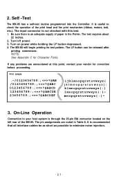
... button depressed. 4. Turn'off power. 3. It is useful to minimize noise injection. -21- It is recommended that all interface cables be released after printing commences. On-Line Operation Connection to your vendor for Character Fonts. Turn on the left rear of paper in Table 8. NOTE: See Appendix C for correction before proceeding. Self -Test The MX-85 has a self-test routine programmed into the Controller. If any problems...
... button depressed. 4. Turn'off power. 3. It is useful to minimize noise injection. -21- It is recommended that all interface cables be released after printing commences. On-Line Operation Connection to your vendor for Character Fonts. Turn on the left rear of paper in Table 8. NOTE: See Appendix C for correction before proceeding. Self -Test The MX-85 has a self-test routine programmed into the Controller. If any problems...

User Manual
Page 27
... button. -22- The MX-85 will stop upon depression of the Carriage Return (CR) or Line Feed (LF) Control codes. 2. When the sensor is activated, the following means: 1. DTR pin 20 Mark (-V) Data Entry - Sounds for 20 seconds Printing - Unaffected NOTE: Buzzer will continue to receive and/or print data. Printing is initiated by the MX-85 is activated when approximately 7 meters (22') of Operation The data...
... button. -22- The MX-85 will stop upon depression of the Carriage Return (CR) or Line Feed (LF) Control codes. 2. When the sensor is activated, the following means: 1. DTR pin 20 Mark (-V) Data Entry - Sounds for 20 seconds Printing - Unaffected NOTE: Buzzer will continue to receive and/or print data. Printing is initiated by the MX-85 is activated when approximately 7 meters (22') of Operation The data...

User Manual
Page 28
... Buzzer - Disabled Indicators - Enabled As soon as 1 K bytes of memory is not in the memory. Sounds for replacement of paper loading, the "On-Line" button should be done with the power on to normal. -23- Upon completion of the paper roll. This will revert to avoid losing any printable characters stored in a memory full condition. 4.3. 4K memory full When the buffer memory reaches 3,996...
... Buzzer - Disabled Indicators - Enabled As soon as 1 K bytes of memory is not in the memory. Sounds for replacement of paper loading, the "On-Line" button should be done with the power on to normal. -23- Upon completion of the paper roll. This will revert to avoid losing any printable characters stored in a memory full condition. 4.3. 4K memory full When the buffer memory reaches 3,996...

User Manual
Page 29
Check to position the paper. 2. Reposition if necessary. Tear off the last message printed, depress the FF button to see that the paper is against the platen and that the paper has not shifted. 5. Paper Tear-Off 1. Hold down the printer cover while tearing the paper. 3. To tear off the Paper Fig. 21 Cutting Paper -24-
Check to position the paper. 2. Reposition if necessary. Tear off the last message printed, depress the FF button to see that the paper is against the platen and that the paper has not shifted. 5. Paper Tear-Off 1. Hold down the printer cover while tearing the paper. 3. To tear off the Paper Fig. 21 Cutting Paper -24-

User Manual
Page 30
... Self-Test. -25- Allow time for it to cool before attempting replacement. 1. Remove the printer cover and cartridge ribbon. 2. Paper dust and particles should be cleaned with a mild detergent and water solution. 3. Turn the head locking lever clockwise and lift the print head straight up. 3. The only user replaceable items are the cartridge ribbon and the print head. Cartridge ribbon replacement is covered in a previous section of cleaning. 1. MAINTENANCE AND PARTS REPLACEMENT Preventative Maintenance of the MX-85...
... Self-Test. -25- Allow time for it to cool before attempting replacement. 1. Remove the printer cover and cartridge ribbon. 2. Paper dust and particles should be cleaned with a mild detergent and water solution. 3. Turn the head locking lever clockwise and lift the print head straight up. 3. The only user replaceable items are the cartridge ribbon and the print head. Cartridge ribbon replacement is covered in a previous section of cleaning. 1. MAINTENANCE AND PARTS REPLACEMENT Preventative Maintenance of the MX-85...

User Manual
Page 31
Fig. 22 Replacement of the directions indicated by arrow to pull the head cable out straight. *Take hold of the cable at the point indicated by arrows and apply force in either of Print Head -26- Print Head Unit Head Lock Lever Carriage A&embly (Side View) Terminal Board Head Connector Be sure to hold this connectar firmly to push in or pull out the head cable.
Fig. 22 Replacement of the directions indicated by arrow to pull the head cable out straight. *Take hold of the cable at the point indicated by arrows and apply force in either of Print Head -26- Print Head Unit Head Lock Lever Carriage A&embly (Side View) Terminal Board Head Connector Be sure to hold this connectar firmly to push in or pull out the head cable.


