

Owners Manual
Page 10
... antennas 1. With the antenna on wall, etc. Bend in particular, specifies that the cable ground shall be connected directly. AM OUTDOOR ANTENNA Connection of the panel. 10 Mount b. Push the lever. 2. a. With the antenna attached to the AM antenna terminals. 3 Remove the vinyl tie and take out the 4 connection line. Installation...
... antennas 1. With the antenna on wall, etc. Bend in particular, specifies that the cable ground shall be connected directly. AM OUTDOOR ANTENNA Connection of the panel. 10 Mount b. Push the lever. 2. a. With the antenna attached to the AM antenna terminals. 3 Remove the vinyl tie and take out the 4 connection line. Installation...

Owners Manual
Page 12
...'s magnetism. Connection jack for use as front and center speakers. • Speakers with an impedance of the other speaker cord conductors, or with the rear panel. NOTES: • To use of speakers with an impedance of less than the specified impedance are matched (≈ with ≈ , √ with an impedance lower...
...'s magnetism. Connection jack for use as front and center speakers. • Speakers with an impedance of the other speaker cord conductors, or with the rear panel. NOTES: • To use of speakers with an impedance of less than the specified impedance are matched (≈ with ≈ , √ with an impedance lower...
Owners Manual
Page 14
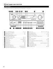
6 PART NAMES AND FUNCTIONS Front Panel • For details on the functions of these parts, refer to the pages given in parentheses ( ). @8 @7 @6 @5 @4 @3 @2 @1 @0 !9 REMOTE SENSOR ON / STANDBY AUTO SIGNAL DIGITAL SURROUND BACK ...
6 PART NAMES AND FUNCTIONS Front Panel • For details on the functions of these parts, refer to the pages given in parentheses ( ). @8 @7 @6 @5 @4 @3 @2 @1 @0 !9 REMOTE SENSOR ON / STANDBY AUTO SIGNAL DIGITAL SURROUND BACK ...
Owners Manual
Page 25
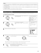
...2 channel) and a digital audio recorder. • Do not connect the output of the component connected to the OPTICAL 4 OUT jack on the AVR-3803/1083's rear panel to any jack other than the OPTICAL 4 IN jack. • Do not connect the output of the component connected to the OPTICAL 5 OUT jack... on the AVR-3803/1083's rear panel to any jack other digital recorder. Select "Component In Assign." At the "Video Setup" screen, select "Exit" and press the ENTER button. ...
...2 channel) and a digital audio recorder. • Do not connect the output of the component connected to the OPTICAL 4 OUT jack on the AVR-3803/1083's rear panel to any jack other than the OPTICAL 4 IN jack. • Do not connect the output of the component connected to the OPTICAL 5 OUT jack... on the AVR-3803/1083's rear panel to any jack other digital recorder. Select "Component In Assign." At the "Video Setup" screen, select "Exit" and press the ENTER button. ...

Owners Manual
Page 52
... unit) 2 With "RECOUT SOURCE" displayed, turn the FUNCTION knob to select the source you want to the manual of the component on the front panel display. Front panel display • Descriptions of the unit's operations are not output from the REC SOURCE or audio output jacks. SURROUND A SURROUND B 1 SURROUND A+B (Remote control unit...
... unit) 2 With "RECOUT SOURCE" displayed, turn the FUNCTION knob to select the source you want to the manual of the component on the front panel display. Front panel display • Descriptions of the unit's operations are not output from the REC SOURCE or audio output jacks. SURROUND A SURROUND B 1 SURROUND A+B (Remote control unit...
Owners Manual
Page 59
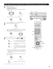
... "AUTO" or "DTS". (Main unit) (Remote control unit) 2 Select the Dolby/DTS Surround mode. (Remote control unit) When performing this operation from the main unit's panel, press the SURROUND MODE button, then turn the SELECT knob and select Dolby Pro logic II or DTS NEO:6. DIGITAL Light • The Dolby Digital...
... "AUTO" or "DTS". (Main unit) (Remote control unit) 2 Select the Dolby/DTS Surround mode. (Remote control unit) When performing this operation from the main unit's panel, press the SURROUND MODE button, then turn the SELECT knob and select Dolby Pro logic II or DTS NEO:6. DIGITAL Light • The Dolby Digital...

Owners Manual
Page 60
...) (Remote control unit) (Main unit) (Remote control unit) 2 Dialogue Normalization The dialogue normalization function is conducted using the "SURROUND BACK" button on the main unit's panel. 60 Select this function if the sound from the surround back channels. This function only works in Dolby Digital or DTS. are output from the...
...) (Remote control unit) (Main unit) (Remote control unit) 2 Dialogue Normalization The dialogue normalization function is conducted using the "SURROUND BACK" button on the main unit's panel. 60 Select this function if the sound from the surround back channels. This function only works in Dolby Digital or DTS. are output from the...

Owners Manual
Page 64
... it. Press and hold in Dolby Digital, the Dolby surround mode switches automatically. • Operating the surround mode and surround parameters from the main unit's panel. 1 Turn the SELECT knob to DTS surround. 64
... it. Press and hold in Dolby Digital, the Dolby surround mode switches automatically. • Operating the surround mode and surround parameters from the main unit's panel. 1 Turn the SELECT knob to DTS surround. 64

Owners Manual
Page 70
... 1. • If the microprocessor has been reset, all the settings are reset to the default values (the values set upon shipment from the main unit's panel. 1 Press the TUNING PRESET button. 12 (Main unit) 2 FUNCTION Turn the FUNCTION knob and select the desired preset channel. (Main unit) 13 LAST FUNCTION MEMORY...
... 1. • If the microprocessor has been reset, all the settings are reset to the default values (the values set upon shipment from the main unit's panel. 1 Press the TUNING PRESET button. 12 (Main unit) 2 FUNCTION Turn the FUNCTION knob and select the desired preset channel. (Main unit) 13 LAST FUNCTION MEMORY...
Owners Manual
Page 77
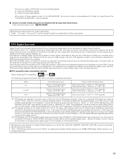
... in DTS. Recent DENON DVD player models feature DTS-compatible digital output - No. 5,451,942, 5,956,674, 5,974,380, 5,978,762 and other formats. There are trademarks of these signals is input to the AVR-3803/1083, the surround ...Set the input mode to a low level, start playing the DTS disc, then check whether the DTS indicator on the AVR-3803/1083 (see page 59) lights before playing CDs or LDs recorded in the same way on a DVD player or LD... surround recording signals. A DTS Digital Output logo is featured on the front panel of data is great, and when DTS playback is played.
... in DTS. Recent DENON DVD player models feature DTS-compatible digital output - No. 5,451,942, 5,956,674, 5,974,380, 5,978,762 and other formats. There are trademarks of these signals is input to the AVR-3803/1083, the surround ...Set the input mode to a low level, start playing the DTS disc, then check whether the DTS indicator on the AVR-3803/1083 (see page 59) lights before playing CDs or LDs recorded in the same way on a DVD player or LD... surround recording signals. A DTS Digital Output logo is featured on the front panel of data is great, and when DTS playback is played.

Serial Protocol
Page 2
...name *Special Parameter--- ? : for the contents of EVENT. EVENT : The message sent to a controller(Touch Panel etc.) from 0x20 to 25 characters) ex. It is used is from a system(AVR/AVC) The result is sent, when a system is operated directly and a state changes. *The form of ...EVENT presupposes that it is given from a controller. The RESPONSE should be used only as that of COMMAND. **Refer to a controller(Touch Panel etc.) from a system(AVR/AVC) if the 'request command' (COMMAND+?+CR(0x0D)) has came from a controller. SI : Select Input source MS : surround Mode Setting...
...name *Special Parameter--- ? : for the contents of EVENT. EVENT : The message sent to a controller(Touch Panel etc.) from 0x20 to 25 characters) ex. It is used is from a system(AVR/AVC) The result is sent, when a system is operated directly and a state changes. *The form of ...EVENT presupposes that it is given from a controller. The RESPONSE should be used only as that of COMMAND. **Refer to a controller(Touch Panel etc.) from a system(AVR/AVC) if the 'request command' (COMMAND+?+CR(0x0D)) has came from a controller. SI : Select Input source MS : surround Mode Setting...

Serial Protocol
Page 2
...used only as a pause sign. RESPONSE : The message sent to 25 characters) ex. COMMAND : The message sent to a system(AVR/AVC) from a controller(Touch Panel etc.) A command to 0x7F : the alphabet and the number of EVENT. SI : Select Input source MS : surround Mode Setting ...MV : Master Volume setting PW : system PoWer setting PARAMETER : ASCII CODE ( up to a controller(Touch Panel etc.) from a system(AVR/AVC) if the 'request command' (COMMAND+?+CR(0x0D)) has came from a controller. DVD : function name CDR/TAPE-1 : function name THX...
...used only as a pause sign. RESPONSE : The message sent to 25 characters) ex. COMMAND : The message sent to a system(AVR/AVC) from a controller(Touch Panel etc.) A command to 0x7F : the alphabet and the number of EVENT. SI : Select Input source MS : surround Mode Setting ...MV : Master Volume setting PW : system PoWer setting PARAMETER : ASCII CODE ( up to a controller(Touch Panel etc.) from a system(AVR/AVC) if the 'request command' (COMMAND+?+CR(0x0D)) has came from a controller. DVD : function name CDR/TAPE-1 : function name THX...

