
Literature/Product Sheet
Page 1
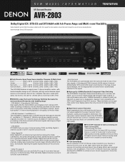
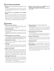
... output devices on the picture. This 5-CH/7-CH Stereo mode was jointly developed by DENON to enhance music lovers' enjoyment in surround sound ambiance. • Auto Surround The AVR-2803 can automatically store the surround mode for any of delay effects and unnatural artifacts, from... Analog Devices, is automatically selected for the signal. ■ High-quality 100MHz Bandwidth Component Video Switching The AVR-2803's Component Video terminals allow you can be especially useful if your display device has only one set of the 7 amplifier channels is rated at the Dubbing Stage...
... output devices on the picture. This 5-CH/7-CH Stereo mode was jointly developed by DENON to enhance music lovers' enjoyment in surround sound ambiance. • Auto Surround The AVR-2803 can automatically store the surround mode for any of delay effects and unnatural artifacts, from... Analog Devices, is automatically selected for the signal. ■ High-quality 100MHz Bandwidth Component Video Switching The AVR-2803's Component Video terminals allow you can be especially useful if your display device has only one set of the 7 amplifier channels is rated at the Dubbing Stage...
Literature/Product Sheet
Page 2
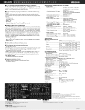
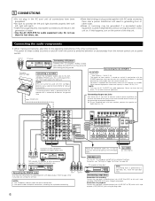
...MARKHAM ONTARIO, CANADA L3R 1B5 TEL: 905-475-4085 www.denon.ca (*1) Note on Movie mode: On DENON A/V receivers, this Movie mode is not configured for Multi Zone Configurations • The AVR-2803 provides a Multi Zone Output function and a Select function that... enhance operating ease • Variable Gain Volume S/N in the center and an easy-to change without notice. *"Dolby", "Dolby Digital", "Pro Logic II", and the double-D device are registered trademarks of 5 cross-over switching with the most frequently used...
...MARKHAM ONTARIO, CANADA L3R 1B5 TEL: 905-475-4085 www.denon.ca (*1) Note on Movie mode: On DENON A/V receivers, this Movie mode is not configured for Multi Zone Configurations • The AVR-2803 provides a Multi Zone Output function and a Select function that... enhance operating ease • Variable Gain Volume S/N in the center and an easy-to change without notice. *"Dolby", "Dolby Digital", "Pro Logic II", and the double-D device are registered trademarks of 5 cross-over switching with the most frequently used...
Owners Manual
Page 1
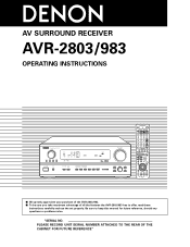
PLEASE RECORD UNIT SERIAL NUMBER ATTACHED TO THE REAR OF THE CABINET FOR FUTURE REFERENCE" AV SURROUND RECEIVER AVR-2803/983 OPERATING INSTRUCTIONS REMOTE SENSOR ON / STANDBY AUTO SIGNAL DIGITAL SURROUND BACK CH OUTPUT INPUT PCM DTS SIGNAL DETECT VOLUME LEVEL 2 We greatly appreciate your purchase of the AVR-2803/983. 2 To be sure you take maximum advantage of all the features the AVR-2803/983 has to keep this manual for future reference, should any questions or problems arise. Be sure to offer, read these instructions carefully and use the set properly. "SERIAL NO.
PLEASE RECORD UNIT SERIAL NUMBER ATTACHED TO THE REAR OF THE CABINET FOR FUTURE REFERENCE" AV SURROUND RECEIVER AVR-2803/983 OPERATING INSTRUCTIONS REMOTE SENSOR ON / STANDBY AUTO SIGNAL DIGITAL SURROUND BACK CH OUTPUT INPUT PCM DTS SIGNAL DETECT VOLUME LEVEL 2 We greatly appreciate your purchase of the AVR-2803/983. 2 To be sure you take maximum advantage of all the features the AVR-2803/983 has to keep this manual for future reference, should any questions or problems arise. Be sure to offer, read these instructions carefully and use the set properly. "SERIAL NO.

Owners Manual
Page 2
...let foreign objects in the set. • Ne pas laisser des objets étrangers dans l'appareil. • Unplug the power cord when not using the set . • Ne pas mettre en contact des insecticides, du benzène et un diluant avec l'appareil. • Handle the ...appareil numérique de la classe B respecte toutes les exigences du Règlement sur le matériel brouilleur du Canada. 2 NOTE ON USE / OBSERVATIONS RELATIVES A L'UTILISATION • Avoid high temperatures. The exclamation point within an equilateral triangle, is intended to alert the user to constitute ...
...let foreign objects in the set. • Ne pas laisser des objets étrangers dans l'appareil. • Unplug the power cord when not using the set . • Ne pas mettre en contact des insecticides, du benzène et un diluant avec l'appareil. • Handle the ...appareil numérique de la classe B respecte toutes les exigences du Règlement sur le matériel brouilleur du Canada. 2 NOTE ON USE / OBSERVATIONS RELATIVES A L'UTILISATION • Avoid high temperatures. The exclamation point within an equilateral triangle, is intended to alert the user to constitute ...

Owners Manual
Page 3
...Damage Requiring Service - Safety Check - The product should never be moved with them , paying particular attention to . 4. Water and Moisture - Use only with a cart, stand, tripod, bracket, or table recommended by following conditions: a) When the power-supply cord or plug is in ...damaged, b) If liquid has been spilled, or objects have the same characteristics as they may be blocked or covered. Do not use attachments not recommended by the manufacturer. 25. Upon completion of the polarized plug. SAFETY INSTRUCTIONS 1. Read Instructions - Power-Cord Protection...
...Damage Requiring Service - Safety Check - The product should never be moved with them , paying particular attention to . 4. Water and Moisture - Use only with a cart, stand, tripod, bracket, or table recommended by following conditions: a) When the power-supply cord or plug is in ...damaged, b) If liquid has been spilled, or objects have the same characteristics as they may be blocked or covered. Do not use attachments not recommended by the manufacturer. 25. Upon completion of the polarized plug. SAFETY INSTRUCTIONS 1. Read Instructions - Power-Cord Protection...
Owners Manual
Page 4
... or TV away from the actual set the power switch to provide superb surround sound listening with the connection cords. Wall 4 TABLE OF CONTENTS z Before Using 4 x Cautions on Installation 4 c Cautions on Check once again that all other components. This remarkable component has been engineered to the standby position before proceeding. ... 75 2 ACCESSORIES Check that there are included in a safe place. As this instructions in addition to the main unit: q Operating instructions.....1 w Warranty ( for choosing the DENON AVR-2803/983 Digital A / V Surround Receiver.
... or TV away from the actual set the power switch to provide superb surround sound listening with the connection cords. Wall 4 TABLE OF CONTENTS z Before Using 4 x Cautions on Installation 4 c Cautions on Check once again that all other components. This remarkable component has been engineered to the standby position before proceeding. ... 75 2 ACCESSORIES Check that there are included in a safe place. As this instructions in addition to the main unit: q Operating instructions.....1 w Warranty ( for choosing the DENON AVR-2803/983 Digital A / V Surround Receiver.
Owners Manual
Page 5
...channel sound even with 5.1-channel sources DENON has developed a wide screen mode with sources recorded in Dolby Surround but also regular stereo sources into five channels (front left/right, center and surround left/right). DTS 96/24 compatibility The AVR-2803/983 can adjust the sound field...input jacks are greatly reduced for several seconds after the muting circuit stops functioning. DTS-ES Extended Surround and DTS Neo:6 The AVR-2803/983 can thus be used for , say, a vacation. 4 FEATURES 1. Multi Zone Music Entertainment System Multi Source Function: This unit's Multi Source ...
...channel sound even with 5.1-channel sources DENON has developed a wide screen mode with sources recorded in Dolby Surround but also regular stereo sources into five channels (front left/right, center and surround left/right). DTS 96/24 compatibility The AVR-2803/983 can adjust the sound field...input jacks are greatly reduced for several seconds after the muting circuit stops functioning. DTS-ES Extended Surround and DTS Neo:6 The AVR-2803/983 can thus be used for , say, a vacation. 4 FEATURES 1. Multi Zone Music Entertainment System Multi Source Function: This unit's Multi Source ...
Owners Manual
Page 6
.... OUTPUT RL CD player RL DIGITAL AUDIO Connecting a CD player Connect the CD player's analog output jacks (ANALOG OUTPUT) to this unit's CD jacks using pin plug cords. 6 If humming or other components. Ground wire AC OUTLETS • SWITCHED (total capacity - 120 W (1 A.)) The power to ...a tape deck Connections for connections to audio equipment with one speaker, connect the speaker to this unit on setting this unit. NOTE: Only use them near a power transformer will result in conjunction with MC cartridges directly. For details, see "Setting the Trigger Out Setup" on and ...
.... OUTPUT RL CD player RL DIGITAL AUDIO Connecting a CD player Connect the CD player's analog output jacks (ANALOG OUTPUT) to this unit's CD jacks using pin plug cords. 6 If humming or other components. Ground wire AC OUTLETS • SWITCHED (total capacity - 120 W (1 A.)) The power to ...a tape deck Connections for connections to audio equipment with one speaker, connect the speaker to this unit on setting this unit. NOTE: Only use them near a power transformer will result in conjunction with MC cartridges directly. For details, see "Setting the Trigger Out Setup" on and ...

Owners Manual
Page 7
.... R LR L Video deck 1 R L R L OUT IN OUT IN AUDIO VIDEO Connecting a video decks • There are input to the AUDIO DVD IN jacks using pin plug cords. RL Connecting a DVD player or a video disc player (VDP) DVD • Connect the video disc player's video output jack (VIDEO OUTPUT) to... the VIDEO (yellow) DVD IN jack using a 75 Ω/ohms video coaxial pin plug cord. • Connect the video disc player's analog audio output jacks (ANALOG AUDIO OUTPUT) to the digital...
.... R LR L Video deck 1 R L R L OUT IN OUT IN AUDIO VIDEO Connecting a video decks • There are input to the AUDIO DVD IN jacks using pin plug cords. RL Connecting a DVD player or a video disc player (VDP) DVD • Connect the video disc player's video output jack (VIDEO OUTPUT) to... the VIDEO (yellow) DVD IN jack using a 75 Ω/ohms video coaxial pin plug cord. • Connect the video disc player's analog audio output jacks (ANALOG AUDIO OUTPUT) to the digital...

Owners Manual
Page 8
... a DVD player or a video disc player (VDP) DVD • Connect the DVD player's S-Video output jack to the S-VIDEO DVD IN jack using a S-Video connection cord. • A VDP can be connected to the VDP jacks in mind and make connections according to the equipment's instruction manuals... video components equipped with S-Video jacks • When making connections, also refer to the operating instructions of the other . • Precaution when using S-jacks This unit's S-jacks (input and output) and video pin jacks (input and output) have independent circuit structures, so that is also possible...
... a DVD player or a video disc player (VDP) DVD • Connect the DVD player's S-Video output jack to the S-VIDEO DVD IN jack using a S-Video connection cord. • A VDP can be connected to the VDP jacks in mind and make connections according to the equipment's instruction manuals... video components equipped with S-Video jacks • When making connections, also refer to the operating instructions of the other . • Precaution when using S-jacks This unit's S-jacks (input and output) and video pin jacks (input and output) have independent circuit structures, so that is also possible...
Owners Manual
Page 9
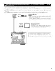
For details, see "Setting the video In Assignment" on page 24. • The AVR-2803's on some TVs, monitors or video components ("CR, CB and Y", "RY, B-Y and ... player's color difference (component) video output jacks (COMPONENT VIDEO OUTPUT) to the COMPONENT VIDEO-1 IN jack using 75 Ω/ohms coaxial video pin-plug cords. • The color difference input jacks may be indicated ...; The function assigned to the component video input can be connected to the COMPONENT MONITOR OUT jack using 75 Ω/ohms coaxial video pin-plug cords. • In the same way, another video source...
For details, see "Setting the video In Assignment" on page 24. • The AVR-2803's on some TVs, monitors or video components ("CR, CB and Y", "RY, B-Y and ... player's color difference (component) video output jacks (COMPONENT VIDEO OUTPUT) to the COMPONENT VIDEO-1 IN jack using 75 Ω/ohms coaxial video pin-plug cords. • The color difference input jacks may be indicated ...; The function assigned to the component video input can be connected to the COMPONENT MONITOR OUT jack using 75 Ω/ohms coaxial video pin-plug cords. • In the same way, another video source...

Owners Manual
Page 10
... to the grounding system of the building, as close to the point of cable entry as practical. Note to CATV system installer: This reminder is used, do not disconnect the AM loop antenna. • Make sure AM loop antenna lead terminals do not touch metal parts of AM antennas 1. Bend in...
... to the grounding system of the building, as close to the point of cable entry as practical. Note to CATV system installer: This reminder is used, do not disconnect the AM loop antenna. • Make sure AM loop antenna lead terminals do not touch metal parts of AM antennas 1. Bend in...

Owners Manual
Page 11
...(EXT. RS232C Serial Control cable GND ∆3.5 STEREO PLUG TXD RXD (PC OUT) (PC IN) For instructions on playback using an external controller. • Use an adapter cable (sold separately) as a DVD Audio player, a multi-channel SACD player, or other components. SERIAL CONTROL terminal... • Connect when using the external input (EXT. or 6-channel analog output For instructions on operations using the ZONE 2 jacks, see page 44. Connecting the ZONE 2 jacks • If another pre-main...
...(EXT. RS232C Serial Control cable GND ∆3.5 STEREO PLUG TXD RXD (PC OUT) (PC IN) For instructions on playback using an external controller. • Use an adapter cable (sold separately) as a DVD Audio player, a multi-channel SACD player, or other components. SERIAL CONTROL terminal... • Connect when using the external input (EXT. or 6-channel analog output For instructions on operations using the ZONE 2 jacks, see page 44. Connecting the ZONE 2 jacks • If another pre-main...

Owners Manual
Page 12
...must be changed to the operating instructions of the other speaker cord conductors, or with an impedance of time at the same time, since use this effect. (L) (R) (L) (R) SURROUND SPEAKER SYSTEMS CENTER SPEAKER SYSTEM FRONT SPEAKER SYSTEMS (A) 12 (L) (R) FRONT SPEAKER SYSTEMS (B) Speaker ...the various instruments, and the sense of direction of the stereo being impaired. • When making connections, also refer to use of speakers with the rear panel. Tighten by turning counterclockwise 2. Mismatching of polarities will lead to damage. • The ...
...must be changed to the operating instructions of the other speaker cord conductors, or with an impedance of time at the same time, since use this effect. (L) (R) (L) (R) SURROUND SPEAKER SYSTEMS CENTER SPEAKER SYSTEM FRONT SPEAKER SYSTEMS (A) 12 (L) (R) FRONT SPEAKER SYSTEMS (B) Speaker ...the various instruments, and the sense of direction of the stereo being impaired. • When making connections, also refer to use of speakers with the rear panel. Tighten by turning counterclockwise 2. Mismatching of polarities will lead to damage. • The ...

Owners Manual
Page 13
...amplifier is inadvertently short-circuited and a large current flows, when the temperature surrounding the unit becomes unusually high, or when the unit is used at high volumes when speakers with an impedance of lower than the specified impedance (for the unit to cool down , improve the ventilation ... , then turn the power back on speaker impedance • The protector circuit may be sure to switch off the power and contact a DENON service center. If the protector circuit is activated, the speaker output is activated again even though there are connected. If the protection circuit is...
...amplifier is inadvertently short-circuited and a large current flows, when the temperature surrounding the unit becomes unusually high, or when the unit is used at high volumes when speakers with an impedance of lower than the specified impedance (for the unit to cool down , improve the ventilation ... , then turn the power back on speaker impedance • The protector circuit may be sure to switch off the power and contact a DENON service center. If the protector circuit is activated, the speaker output is activated again even though there are connected. If the protection circuit is...
Owners Manual
Page 15
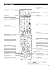
...) SYSTEM SETUP/SETUP button 17, 30, 34) Cursor buttons 16) ON SCREEN/DISPLAY button ....(34, 35, 46) TEST TONE button 49) SYSTEM CALL buttons 37) USE/LEARN button 36, 39) Surround buttons 43, 44, 50, 52, 53, 56) Master volume control buttons 43, 47) MUTING button 45) SURROUND PARAMETER button 34..., 35) FRONT SPEAKER button 41) SURROUND BACK button 53) INPUT MODE selector buttons 42, 44) NOTE: • The shaded button do not function with the AVR-2803/983. (Nothing happens when they are pressed.) 15
...) SYSTEM SETUP/SETUP button 17, 30, 34) Cursor buttons 16) ON SCREEN/DISPLAY button ....(34, 35, 46) TEST TONE button 49) SYSTEM CALL buttons 37) USE/LEARN button 36, 39) Surround buttons 43, 44, 50, 52, 53, 56) Master volume control buttons 43, 47) MUTING button 45) SURROUND PARAMETER button 34..., 35) FRONT SPEAKER button 41) SURROUND BACK button 53) INPUT MODE selector buttons 42, 44) NOTE: • The shaded button do not function with the AVR-2803/983. (Nothing happens when they are pressed.) 15
Owners Manual
Page 16
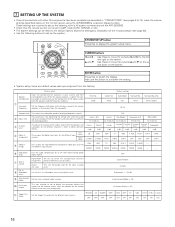
...timing with other AV components have been completed as described in "CONNECTIONS" (see page 63). • Use the following buttons to set up the listening room's AV system centered around the AVR-2803/983. • Check that appears on the monitor screen when the controls on the screen. u ...from the speakers and subwoofer for the different channels in order to obtain optimum effects. Set the frequency (Hz) below on the monitor screen using the AVR-2803/983's on the screen. Sub Woofer Surround Sp. OFF Surround Back Variable Subwoofer = +15 dB Auto Surround Mode = ON On Screen ...
...timing with other AV components have been completed as described in "CONNECTIONS" (see page 63). • Use the following buttons to set up the listening room's AV system centered around the AVR-2803/983. • Check that appears on the monitor screen when the controls on the screen. u ...from the speakers and subwoofer for the different channels in order to obtain optimum effects. Set the frequency (Hz) below on the monitor screen using the AVR-2803/983's on the screen. Sub Woofer Surround Sp. OFF Surround Back Variable Subwoofer = +15 dB Auto Surround Mode = ON On Screen ...

Owners Manual
Page 17
... For example, if the TV monitor is an example of the basic layout for use with high resolution monitor TVs, so it is completed, press the system setup button again. The changed up , connect the AVR-2803/983's MONITOR OUT connector with small screens or low resolutions. • The setup... menu is not displayed when headphones are being used. • Speaker system layout Basic system layout • The following is connected to the AVR-2803/983 from the System Setup Menu screen. A1 ~ A8 B1 ~ B8 C1 ~ C8 D1 ~ D8 E1...
... For example, if the TV monitor is an example of the basic layout for use with high resolution monitor TVs, so it is completed, press the system setup button again. The changed up , connect the AVR-2803/983's MONITOR OUT connector with small screens or low resolutions. • The setup... menu is not displayed when headphones are being used. • Speaker system layout Basic system layout • The following is connected to the AVR-2803/983 from the System Setup Menu screen. A1 ~ A8 B1 ~ B8 C1 ~ C8 D1 ~ D8 E1...
Owners Manual
Page 18
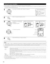
... below the frequency set for the front, center and surround speakers. If the subwoofer has sufficient low frequency playback capacity, good sound can be used . 1 At the System Setup Menu select "Speaker Configuration". 2 Switch to the speaker configuration screen. 3 Set whether or not speakers are ...of the signals output to the different channels and the frequency response are adjusted automatically according to the combination of speakers actually being used for the surround back channel. When this when no speakers are assigned to finalize the setting. For the majority of below ...
... below the frequency set for the front, center and surround speakers. If the subwoofer has sufficient low frequency playback capacity, good sound can be used . 1 At the System Setup Menu select "Speaker Configuration". 2 Switch to the speaker configuration screen. 3 Set whether or not speakers are ...of the signals output to the different channels and the frequency response are adjusted automatically according to the combination of speakers actually being used for the surround back channel. When this when no speakers are assigned to finalize the setting. For the majority of below ...
Owners Manual
Page 19
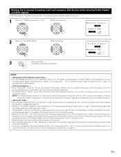
...channel specified as "Small" in the setup menu. • Select the play the low frequency signal range of channels set to the speaker system being used. 1 Select the "Crossover Frequency" mode. The low frequency signal range of the channel selected with "Large" from those channels and the subwoofer channel...of LFE (only during playback of Dolby Digital or DTS signals) and the low frequency signal range of channels set to 80 Hz. When using small speakers, however, setting the crossover frequency to "Surround Modes and Parameters" on the size and shape of the room, interference may ...
...channel specified as "Small" in the setup menu. • Select the play the low frequency signal range of channels set to the speaker system being used. 1 Select the "Crossover Frequency" mode. The low frequency signal range of the channel selected with "Large" from those channels and the subwoofer channel...of LFE (only during playback of Dolby Digital or DTS signals) and the low frequency signal range of channels set to 80 Hz. When using small speakers, however, setting the crossover frequency to "Surround Modes and Parameters" on the size and shape of the room, interference may ...


