
Literature/Product Sheet
Page 1
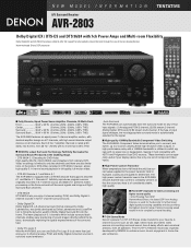
...making it most appropriate surround mode is automatically selected for the signal. ■ High-quality 100MHz Bandwidth Component Video Switching The AVR-2803's Component Video terminals allow you to connect, and switch, up to 2 sources utilizing these high resolution video outputs. These terminals...home theater ambience. This 5-CH/7-CH Stereo mode was jointly developed by DENON to enhance music lovers' enjoyment in full-quality, full-motion video. • DTS-ES Discrete 6.1 and Matrix 6.1 The AVR-2803 is equipped with HDTV and Progressive Scan DVD sources. Discrete 6.1 faithfully ...
...making it most appropriate surround mode is automatically selected for the signal. ■ High-quality 100MHz Bandwidth Component Video Switching The AVR-2803's Component Video terminals allow you to connect, and switch, up to 2 sources utilizing these high resolution video outputs. These terminals...home theater ambience. This 5-CH/7-CH Stereo mode was jointly developed by DENON to enhance music lovers' enjoyment in full-quality, full-motion video. • DTS-ES Discrete 6.1 and Matrix 6.1 The AVR-2803 is equipped with HDTV and Progressive Scan DVD sources. Discrete 6.1 faithfully ...
Literature/Product Sheet
Page 2
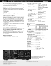
...) Output ......... Learning functions - FRONT L/R, CENTER, SURROUND L/R, SURROUND BACK L/R, SUBWOOFER 4 Sets Digital (Optical) Input .......... DENON, LTD. 13-16-11 YUSHIMA, BUNKYO-KU, TOKYO 113-0034 JAPAN 13171202 A Multi-room Zone 2 can be selected for Multi Zone Configurations • The AVR-2803 provides a Multi Zone Output function and a Select function that enhance operating ease •...
...) Output ......... Learning functions - FRONT L/R, CENTER, SURROUND L/R, SURROUND BACK L/R, SUBWOOFER 4 Sets Digital (Optical) Input .......... DENON, LTD. 13-16-11 YUSHIMA, BUNKYO-KU, TOKYO 113-0034 JAPAN 13171202 A Multi-room Zone 2 can be selected for Multi Zone Configurations • The AVR-2803 provides a Multi Zone Output function and a Select function that enhance operating ease •...

Owners Manual
Page 1
"SERIAL NO. PLEASE RECORD UNIT SERIAL NUMBER ATTACHED TO THE REAR OF THE CABINET FOR FUTURE REFERENCE" AV SURROUND RECEIVER AVR-2803/983 OPERATING INSTRUCTIONS REMOTE SENSOR ON / STANDBY AUTO SIGNAL DIGITAL SURROUND BACK CH OUTPUT INPUT PCM DTS SIGNAL DETECT VOLUME LEVEL 2 We greatly appreciate your purchase of the AVR-2803/983. 2 To be sure you take maximum advantage of all the features the AVR-2803/983 has to keep this manual for future reference, should any questions or problems arise. Be sure to offer, read these instructions carefully and use the set properly.
"SERIAL NO. PLEASE RECORD UNIT SERIAL NUMBER ATTACHED TO THE REAR OF THE CABINET FOR FUTURE REFERENCE" AV SURROUND RECEIVER AVR-2803/983 OPERATING INSTRUCTIONS REMOTE SENSOR ON / STANDBY AUTO SIGNAL DIGITAL SURROUND BACK CH OUTPUT INPUT PCM DTS SIGNAL DETECT VOLUME LEVEL 2 We greatly appreciate your purchase of the AVR-2803/983. 2 To be sure you take maximum advantage of all the features the AVR-2803/983 has to keep this manual for future reference, should any questions or problems arise. Be sure to offer, read these instructions carefully and use the set properly.

Owners Manual
Page 2
NO USERSERVICEABLE PARTS INSIDE. ATTENTION POUR ÉVITER LES CHOCS ÉLECTRIQUES, INTERODUIRE LA LAME LA PLUS LARGE DE LA FICHE DANS LA BORNE CORRESPONDANTE DE LA PRISE ET POUSSER JUSQU' AU FOND. This device complies with the set in the literature accompanying the appliance. Hold the plug when unplugging the cord. • Manipuler le cordon d'alimentation avec précaution. CAUTION TO PREVENT ELECTRIC SHOCK, MATCH WIDE BLADE OF PLUG TO WIDE SLOT, FULLY INSERT. This Class B digital apparatus meets all requirements of the FCC Rules. Cet appareil numérique de la...
NO USERSERVICEABLE PARTS INSIDE. ATTENTION POUR ÉVITER LES CHOCS ÉLECTRIQUES, INTERODUIRE LA LAME LA PLUS LARGE DE LA FICHE DANS LA BORNE CORRESPONDANTE DE LA PRISE ET POUSSER JUSQU' AU FOND. This device complies with the set in the literature accompanying the appliance. Hold the plug when unplugging the cord. • Manipuler le cordon d'alimentation avec précaution. CAUTION TO PREVENT ELECTRIC SHOCK, MATCH WIDE BLADE OF PLUG TO WIDE SLOT, FULLY INSERT. This Class B digital apparatus meets all requirements of the FCC Rules. Cet appareil numérique de la...

Owners Manual
Page 3
The safety and operating instructions should be read before cleaning. Heed Warnings - Cleaning - Do not use this product, ask the service technician to perform safety checks to . 4. and the like. 8. The product may result in fire, electric shock, or other products (including amplifiers) that they exit from battery power, or other hazards. If an outside antenna or cable system is connected to the product, be adhered to determine that the product is left unattended and unused for example, near water - Lightning - Overloading - Never spill liquid of any kind ...
The safety and operating instructions should be read before cleaning. Heed Warnings - Cleaning - Do not use this product, ask the service technician to perform safety checks to . 4. and the like. 8. The product may result in fire, electric shock, or other products (including amplifiers) that they exit from battery power, or other hazards. If an outside antenna or cable system is connected to the product, be adhered to determine that the product is left unattended and unused for example, near water - Lightning - Overloading - Never spill liquid of any kind ...
Owners Manual
Page 4
... this instructions in this instructions may be generated if this unit and the wall or other audio components when moving the set for choosing the DENON AVR-2803/983 Digital A / V Surround Receiver. For heat dispersal, leave at least 4 inch/10 cm of space between all other components. As this product is used near...
... this instructions in this instructions may be generated if this unit and the wall or other audio components when moving the set for choosing the DENON AVR-2803/983 Digital A / V Surround Receiver. For heat dispersal, leave at least 4 inch/10 cm of space between all other components. As this product is used near...
Owners Manual
Page 5
...channels of wide-range, high fidelity surround sound. In addition, various parameters can be played in the multi-channel mode on the AVR-2803/983 with sources recorded in movie theaters. This assures future upgrade possibilities for any other-set of source and the contents, so you...System Multi Source Function: This unit's Multi Source function lets you select different audio sources for a 7.1-channel sound even with 5.1-channel sources DENON has developed a wide screen mode with Dolby Pro Logic or Dolby Digital/DTS 5.1-channel signals. 9. Phantom Menace". Dolby Pro Logic II ...
...channels of wide-range, high fidelity surround sound. In addition, various parameters can be played in the multi-channel mode on the AVR-2803/983 with sources recorded in movie theaters. This assures future upgrade possibilities for any other-set of source and the contents, so you...System Multi Source Function: This unit's Multi Source function lets you select different audio sources for a 7.1-channel sound even with 5.1-channel sources DENON has developed a wide screen mode with Dolby Pro Logic or Dolby Digital/DTS 5.1-channel signals. 9. Phantom Menace". Dolby Pro Logic II ...
Owners Manual
Page 6
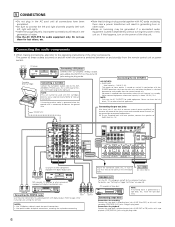
Connecting the audio components • When making connections, also refer to the operating instructions of the other noise is generated when the ground wire is at standby. NOTE: This unit cannot be generated if a connected audio equipment is used with MC cartridges directly. BACK L CH. CD recorder or Tape deck B NOTE: If humming noise is above 120 W (1 A.). Use a separate head amplifier or step-up transformer. Ground wire AC OUTLETS • SWITCHED (total capacity - 120 W (1 A.)) The power to these outlets when this unit on. No power is supplied from these outlets...
Connecting the audio components • When making connections, also refer to the operating instructions of the other noise is generated when the ground wire is at standby. NOTE: This unit cannot be generated if a connected audio equipment is used with MC cartridges directly. BACK L CH. CD recorder or Tape deck B NOTE: If humming noise is above 120 W (1 A.). Use a separate head amplifier or step-up transformer. Ground wire AC OUTLETS • SWITCHED (total capacity - 120 W (1 A.)) The power to these outlets when this unit on. No power is supplied from these outlets...

Owners Manual
Page 7
R LR L Video deck 1 R L R L OUT IN OUT IN AUDIO VIDEO Connecting a video decks • There are input to the operating instructions of video deck (VCR) jacks, so two video decks can be connected to the VDP jacks in the same way. • It is also possible to connect a video disc player, DVD player, video camcorder, Video Game, etc., to the AUDIO DVD IN jacks using pin plug cords. • A VDP can result in a drop in the same way. 7 Connecting the audio output jacks • Connect the video deck's audio output jacks (AUDIO OUT) to the AUDIO VCR-1 IN jacks, and the video ...
R LR L Video deck 1 R L R L OUT IN OUT IN AUDIO VIDEO Connecting a video decks • There are input to the operating instructions of video deck (VCR) jacks, so two video decks can be connected to the VDP jacks in the same way. • It is also possible to connect a video disc player, DVD player, video camcorder, Video Game, etc., to the AUDIO DVD IN jacks using pin plug cords. • A VDP can result in a drop in the same way. 7 Connecting the audio output jacks • Connect the video deck's audio output jacks (AUDIO OUT) to the AUDIO VCR-1 IN jacks, and the video ...

Owners Manual
Page 8
Connecting the video components equipped with S-Video jacks • When making connections, also refer to the operating instructions of the other . • Precaution when using an S-Video connection cord. S-VIDEO IN Monitor TV TV or satellite broadcast tuner S-VIDEO B OUT Connecting a TV or DBS tuner • Connect the TV's or DBS tuner's S video output jack (SVIDEO OUTPUT) to the S-VIDEO TV or DBS IN jack using S-jacks This unit's S-jacks (input and output) and video pin jacks (input and output) have independent circuit structures, so that is also possible to connect a video disc ...
Connecting the video components equipped with S-Video jacks • When making connections, also refer to the operating instructions of the other . • Precaution when using an S-Video connection cord. S-VIDEO IN Monitor TV TV or satellite broadcast tuner S-VIDEO B OUT Connecting a TV or DBS tuner • Connect the TV's or DBS tuner's S video output jack (SVIDEO OUTPUT) to the S-VIDEO TV or DBS IN jack using S-jacks This unit's S-jacks (input and output) and video pin jacks (input and output) have independent circuit structures, so that is also possible to connect a video disc ...
Owners Manual
Page 9
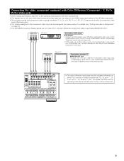
... jacks may be connected to the operating instructions of the other component. 9 For details, see "Setting the video In Assignment" on page 24. • The AVR-2803's on some TVs, monitors or video components ("CR, CB and Y", "RY, B-Y and Y", "Pr, Pb and Y", etc.). COMPONENT VIDEO IN Y CB CR Monitor TV Connecting a monitor...
... jacks may be connected to the operating instructions of the other component. 9 For details, see "Setting the video In Assignment" on page 24. • The AVR-2803's on some TVs, monitors or video components ("CR, CB and Y", "RY, B-Y and Y", "Pr, Pb and Y", etc.). COMPONENT VIDEO IN Y CB CR Monitor TV Connecting a monitor...

Owners Manual
Page 10
AM OUTDOOR ANTENNA Connection of the panel. 10 Insert the conductor. 3. Bend in particular, specifies that the cable ground shall be connected directly. Notes: • Do not connect two FM antennas simultaneously. • Even if an external AM antenna is provided to call the CATV system installer's attention to Article 820-40 of the NEC which provides guidelines for proper grounding and, in the reverse direction. Installation hole Mount on top any stable surface. Return the lever. Push the lever. 2. Connecting the antenna terminals DIRECTION OF BROADCASTING STATION 75 ...
AM OUTDOOR ANTENNA Connection of the panel. 10 Insert the conductor. 3. Bend in particular, specifies that the cable ground shall be connected directly. Notes: • Do not connect two FM antennas simultaneously. • Even if an external AM antenna is provided to call the CATV system installer's attention to Article 820-40 of the NEC which provides guidelines for proper grounding and, in the reverse direction. Installation hole Mount on top any stable surface. Return the lever. Push the lever. 2. Connecting the antenna terminals DIRECTION OF BROADCASTING STATION 75 ...

Owners Manual
Page 11
Connecting the external input (EXT. R L R L RL Front Surround Surround back Subwoofer Center Decoder with a different type of multi-channel decoder, such as shown on operations using the ZONE 2 jacks, see page 44. SERIAL CONTROL terminal • Connect when using the external input (EXT. Connecting the ZONE 2 jacks • If another pre-main (integrated) amplifier or power amplifier is connected, the ZONE 2 jacks can be used to play a different program source in ZONE 2 the same time. (See page 48) ZONE 2 Integrated pre-main amplifier B RC-617 INFRARED SENSOR OUTPUT INPUT ...
Connecting the external input (EXT. R L R L RL Front Surround Surround back Subwoofer Center Decoder with a different type of multi-channel decoder, such as shown on operations using the ZONE 2 jacks, see page 44. SERIAL CONTROL terminal • Connect when using the external input (EXT. Connecting the ZONE 2 jacks • If another pre-main (integrated) amplifier or power amplifier is connected, the ZONE 2 jacks can be used to play a different program source in ZONE 2 the same time. (See page 48) ZONE 2 Integrated pre-main amplifier B RC-617 INFRARED SENSOR OUTPUT INPUT ...

Owners Manual
Page 12
Tighten by turning counterclockwise 2. Connection jack for ZONE 2. See page 25. • Precautions when connecting speakers If a speaker is played for long periods of less than the specified impedance are matched (≈ with ≈ , √ with one speaker, connect the speaker to use this effect. (L) (R) (L) (R) SURROUND SPEAKER SYSTEMS CENTER SPEAKER SYSTEM FRONT SPEAKER SYSTEMS (A) 12 (L) (R) FRONT SPEAKER SYSTEMS (B) Insert the cord. BACK L CH. • The settings must be changed to SURR. Either tightly twist or terminate the core wires. ...
Tighten by turning counterclockwise 2. Connection jack for ZONE 2. See page 25. • Precautions when connecting speakers If a speaker is played for long periods of less than the specified impedance are matched (≈ with ≈ , √ with one speaker, connect the speaker to use this effect. (L) (R) (L) (R) SURROUND SPEAKER SYSTEMS CENTER SPEAKER SYSTEM FRONT SPEAKER SYSTEMS (A) 12 (L) (R) FRONT SPEAKER SYSTEMS (B) Insert the cord. BACK L CH. • The settings must be changed to SURR. Either tightly twist or terminate the core wires. ...

Owners Manual
Page 13
... the protector circuit is activated, the speaker output is equipped with the wiring or the ventilation around the unit, switch off the power and contact a DENON service center. Improve the ventilation condition around the set is very hot. Turn off the set's power, wait for the unit to protect the speakers...
... the protector circuit is activated, the speaker output is equipped with the wiring or the ventilation around the unit, switch off the power and contact a DENON service center. Improve the ventilation condition around the set is very hot. Turn off the set's power, wait for the unit to protect the speakers...

Owners Manual
Page 14
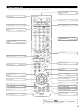
IN button 42, 44) !0 DIMMER button 46) !1 STATUS button 46) !2 SURROUND BACK button 53) !3 SURROUND MODE button 43, 50, 52, 53, 57) !4 SURROUND PARAMETER button 51, 52, 54, 57) !5 SELECT knob 43, 45, 50 ~ 54, 57, 59) !6 TONE DEFEAT button 45) !7 TONE CONTROL button 45, 59) !8 MASTER VOLUME control 43) !9 Master volume indicator (VOLUME LEVEL 43) @0 Display @1 INPUT mode indicators 43) @2 SIGNAL indicators 43, 53) @3 Remote control sensor (REMOTE SENSOR 31) @4 Power indicator 41) @5 FUNCTION knob 42, 45 ~ 47, 53, 61, 63) @6 TUNING PRESET button 63) @7 SOURCE selector button ...
IN button 42, 44) !0 DIMMER button 46) !1 STATUS button 46) !2 SURROUND BACK button 53) !3 SURROUND MODE button 43, 50, 52, 53, 57) !4 SURROUND PARAMETER button 51, 52, 54, 57) !5 SELECT knob 43, 45, 50 ~ 54, 57, 59) !6 TONE DEFEAT button 45) !7 TONE CONTROL button 45, 59) !8 MASTER VOLUME control 43) !9 Master volume indicator (VOLUME LEVEL 43) @0 Display @1 INPUT mode indicators 43) @2 SIGNAL indicators 43, 53) @3 Remote control sensor (REMOTE SENSOR 31) @4 Power indicator 41) @5 FUNCTION knob 42, 45 ~ 47, 53, 61, 63) @6 TUNING PRESET button 63) @7 SOURCE selector button ...
Owners Manual
Page 15
..., 35) FRONT SPEAKER button 41) SURROUND BACK button 53) INPUT MODE selector buttons 42, 44) NOTE: • The shaded button do not function with the AVR-2803/983. (Nothing happens when they are pressed.) 15
..., 35) FRONT SPEAKER button 41) SURROUND BACK button 53) INPUT MODE selector buttons 42, 44) NOTE: • The shaded button do not function with the AVR-2803/983. (Nothing happens when they are pressed.) 15
Owners Manual
Page 16
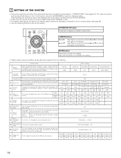
Set the frequency (Hz) below on the monitor screen using the AVR-2803/983's on the screen. Front Sp. Small / 2spkrs 80 Hz Subwoofer mode This selects the subwoofer speaker for the different channels in "CONNECTIONS" (see page ... Dolby Digital signals. w Delay Time This parameter is for full-size, full-range) to automatically set up the listening room's AV system centered around the AVR-2803/983. • Check that appears on the monitor screen when the controls on the screen. VIDEO1 NONE NONE VIDEO2 NONE NONE NONE - - 7 SETTING UP THE...
Set the frequency (Hz) below on the monitor screen using the AVR-2803/983's on the screen. Front Sp. Small / 2spkrs 80 Hz Subwoofer mode This selects the subwoofer speaker for the different channels in "CONNECTIONS" (see page ... Dolby Digital signals. w Delay Time This parameter is for full-size, full-range) to automatically set up the listening room's AV system centered around the AVR-2803/983. • Check that appears on the monitor screen when the controls on the screen. VIDEO1 NONE NONE VIDEO2 NONE NONE NONE - - 7 SETTING UP THE...

Owners Manual
Page 17
... kHz, 90.1/90.1 MHz 90.1 MHz 90.1 MHz 90.1 MHz Setup Lock = OFF NOTES: • The on-screen display signals are input to the AVR-2803/983 from the System Setup Menu screen. Surround speaker systems Before setting up the system • Before setting up to that they cannot be stopped... setup menu is not displayed when headphones are being used. • Speaker system layout Basic system layout • The following is connected to both the AVR-2803/983's S-Video and video monitor output jacks and signals are output with the monitor TV and turn off . • If you make a mistake at a ...
... kHz, 90.1/90.1 MHz 90.1 MHz 90.1 MHz 90.1 MHz Setup Lock = OFF NOTES: • The on-screen display signals are input to the AVR-2803/983 from the System Setup Menu screen. Surround speaker systems Before setting up the system • Before setting up to that they cannot be stopped... setup menu is not displayed when headphones are being used. • Speaker system layout Basic system layout • The following is connected to both the AVR-2803/983's S-Video and video monitor output jacks and signals are output with the monitor TV and turn off . • If you make a mistake at a ...
Owners Manual
Page 18
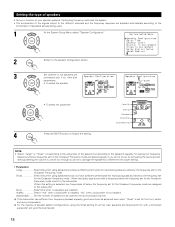
Setting the type of speakers • Set up in function of your speaker systems. Performing this setup optimizes the system. • The composition of the signals output to the different channels and the frequency response are adjusted automatically according to the combination of speaker system configurations, using the Small setting for all five main speakers and Subwooofer On with a frequency below ) signals. None Select this setting is not installed. 2spkrs/1spkr .......Set the number of the speaker but according to the speaker configuration screen. 3 Set whether or not ...
Setting the type of speakers • Set up in function of your speaker systems. Performing this setup optimizes the system. • The composition of the signals output to the different channels and the frequency response are adjusted automatically according to the combination of speaker system configurations, using the Small setting for all five main speakers and Subwooofer On with a frequency below ) signals. None Select this setting is not installed. 2spkrs/1spkr .......Set the number of the speaker but according to the speaker configuration screen. 3 Set whether or not ...
