Owners Manual
Page 1
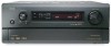
... ATTACHED TO THE REAR OF THE CABINET FOR FUTURE REFERENCE" AV SURROUND RECEIVER AVR-4802R OPERATING INSTRUCTIONS INPUT SELECTOR ON/STANDBY HOME THX CINEMA PURE DIRECT REMOTE SENSOR ON/STANDBY SIGNAL DIGITAL SURROUND BACK CH PURE SIGNAL DIRECT OUTPUT DETECT INPUT AUTO PCM DTS A B SURROUND SPEAKER ES DSCRT DVD VOLUME LEVEL DIGITAL MASTER VOLUME AMP 2 We...
... ATTACHED TO THE REAR OF THE CABINET FOR FUTURE REFERENCE" AV SURROUND RECEIVER AVR-4802R OPERATING INSTRUCTIONS INPUT SELECTOR ON/STANDBY HOME THX CINEMA PURE DIRECT REMOTE SENSOR ON/STANDBY SIGNAL DIGITAL SURROUND BACK CH PURE SIGNAL DIRECT OUTPUT DETECT INPUT AUTO PCM DTS A B SURROUND SPEAKER ES DSCRT DVD VOLUME LEVEL DIGITAL MASTER VOLUME AMP 2 We...
Owners Manual
Page 4
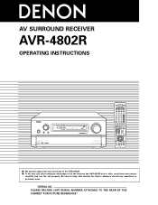
...8226; Install this manual before proceeding. 2 INTRODUCTION Thank you for North America model only )........1 e Service station list 1 t AC cord ........1 y Remote control unit (RC-932) ........1 u R6P/AA batteries ...........3 i AM loop antenna ........1 r List of preset codes ......1 o FM indoor antenna ...surround sound listening with the connection cords. Operation 46~55 ⁄0 Surround 56~67 ⁄1 DENON Original Surround Modes 68~72 ⁄2 Listening to the main unit: q Operating instructions 1 w Warranty ( for choosing the DENON AVR-4802R Digital Surround A / V receiver...
...8226; Install this manual before proceeding. 2 INTRODUCTION Thank you for North America model only )........1 e Service station list 1 t AC cord ........1 y Remote control unit (RC-932) ........1 u R6P/AA batteries ...........3 i AM loop antenna ........1 r List of preset codes ......1 o FM indoor antenna ...surround sound listening with the connection cords. Operation 46~55 ⁄0 Surround 56~67 ⁄1 DENON Original Surround Modes 68~72 ⁄2 Listening to the main unit: q Operating instructions 1 w Warranty ( for choosing the DENON AVR-4802R Digital Surround A / V receiver...
Owners Manual
Page 6
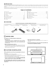
...A.) NOTE: Only use Ground wire Connecting a turntable Connect the turntable's output cord to the AVR-4802R's PHONO jacks, the L (left) plug to the L jack, the R (right) plug...Ω A + B 8~16Ω L L SPEAKER SYSTEMS FRONT L SURROUND -A L SURROUND -B L SB / MULTI L AC OUTLETS POWER AMP OUT OUT IN ROOM TO ROOM REMOTE CONTROL R EXT. NOTE: This unit cannot be generated if a connected audio... standby. Incomplete connections will result in the generation of the front, center, surround and surround back sound channels, or for connection to increase the power of noise. • Use the...
...A.) NOTE: Only use Ground wire Connecting a turntable Connect the turntable's output cord to the AVR-4802R's PHONO jacks, the L (left) plug to the L jack, the R (right) plug...Ω A + B 8~16Ω L L SPEAKER SYSTEMS FRONT L SURROUND -A L SURROUND -B L SB / MULTI L AC OUTLETS POWER AMP OUT OUT IN ROOM TO ROOM REMOTE CONTROL R EXT. NOTE: This unit cannot be generated if a connected audio... standby. Incomplete connections will result in the generation of the front, center, surround and surround back sound channels, or for connection to increase the power of noise. • Use the...
Owners Manual
Page 8
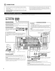
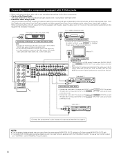
... video output jack (S-VIDEO OUTPUT) to the S-VIDEO TV, DBS/SAT IN jack using S jack connection cords. S-VIDEO IN Monitor TV SPEAKER SYSTEMS FRONT R CENTER SURROUND -A R SURROUND -B R SB / MULTI R LOOP ANT. AUX VCR-1 VCR-2 VCR-3 VCR-1 VCR-2 VCR-3 1-MONITOR-2 SAT SL VIDEO SBL Connecting a monitor TV MONITOR OUT... mind and make connections according to the equipment's instruction manuals. S-VIDEO IN OUT Video deck 2 POWER AMP OUT OUT IN ROOM TO ROOM REMOTE CONTROL Connecting the video decks • Connect the video deck's S output jack (S-OUT) to the S-VIDEO VCR-1 IN jack and the ...
... video output jack (S-VIDEO OUTPUT) to the S-VIDEO TV, DBS/SAT IN jack using S jack connection cords. S-VIDEO IN Monitor TV SPEAKER SYSTEMS FRONT R CENTER SURROUND -A R SURROUND -B R SB / MULTI R LOOP ANT. AUX VCR-1 VCR-2 VCR-3 VCR-1 VCR-2 VCR-3 1-MONITOR-2 SAT SL VIDEO SBL Connecting a monitor TV MONITOR OUT... mind and make connections according to the equipment's instruction manuals. S-VIDEO IN OUT Video deck 2 POWER AMP OUT OUT IN ROOM TO ROOM REMOTE CONTROL Connecting the video decks • Connect the video deck's S output jack (S-OUT) to the S-VIDEO VCR-1 IN jack and the ...
Owners Manual
Page 10
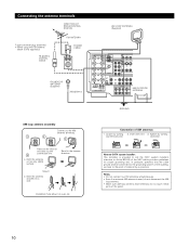
...IN PB/CB PR/CR FM COAX. 75Ω SW SR C DVD VDP TV SL SURROUND -B R SB / MULTI R SBR ANTENNA SIGNAL PHONO GND L SBL I CD DVD VDP TV POWER AMP OUT OUT IN ROOM TO ROOM REMOTE CONTROL R EXT. Notes: • Do not connect two FM antennas simultaneously. •... 75 Ω/ohms COAXIAL CABLE FM ANTENNA FEEDER CABLE FM INDOOR ANTENNA (Supplied) 300 Ω/ohms AM LOOP ANTENNA (Supplied) SPEAKER SYSTEMS FRONT R CENTER SURROUND -A R LOOP ANT. With the antenna attached to the AM antenna terminals. 1 2 3 Remove the vinyl tie and take out the connection line. 4 a....
...IN PB/CB PR/CR FM COAX. 75Ω SW SR C DVD VDP TV SL SURROUND -B R SB / MULTI R SBR ANTENNA SIGNAL PHONO GND L SBL I CD DVD VDP TV POWER AMP OUT OUT IN ROOM TO ROOM REMOTE CONTROL R EXT. Notes: • Do not connect two FM antennas simultaneously. •... 75 Ω/ohms COAXIAL CABLE FM ANTENNA FEEDER CABLE FM INDOOR ANTENNA (Supplied) 300 Ω/ohms AM LOOP ANTENNA (Supplied) SPEAKER SYSTEMS FRONT R CENTER SURROUND -A R LOOP ANT. With the antenna attached to the AM antenna terminals. 1 2 3 Remove the vinyl tie and take out the connection line. 4 a....

Owners Manual
Page 11
... OUT CDR/ MULTI TAPE ZONE L L AC IN SPEAKER IMPEDANCE FRONT, CENTER, SB / MULTI 6~16Ω SURROUND A OR B 6~16Ω A + B 8~16Ω -A L SURROUND -B L SB / MULTI L AC OUTLETS POWER AMP OUT OUT IN ROOM TO ROOM REMOTE CONTROL R EXT. or 6-channel analog output For instructions on operations using the external input (EXT. AV 120V 60Hz Extension...
... OUT CDR/ MULTI TAPE ZONE L L AC IN SPEAKER IMPEDANCE FRONT, CENTER, SB / MULTI 6~16Ω SURROUND A OR B 6~16Ω A + B 8~16Ω -A L SURROUND -B L SB / MULTI L AC OUTLETS POWER AMP OUT OUT IN ROOM TO ROOM REMOTE CONTROL R EXT. or 6-channel analog output For instructions on operations using the external input (EXT. AV 120V 60Hz Extension...

Owners Manual
Page 13
...making connections, also refer to left channel. (L) (R) SURROUND SPEAKER SYSTEMS (B) 13 If this should happen, move the speaker away to a position where it does not have this effect. (L) (R) SURROUND BACK SPEAKER SYSTEMS NOTE: When using only one surround back speaker, connect it to ... IN SPEAKER IMPEDANCE FRONT, CENTER, SB / MULTI 6~16Ω SURROUND A OR B 6~16Ω A + B 8~16Ω SPEAKER SYSTEMS FRONT L SURROUND -A L SURROUND -B L SB / MULTI L AC OUTLETS POWER AMP OUT OUT IN ROOM TO ROOM REMOTE CONTROL R EXT. AV 120V 60Hz • Precautions when placing speakers...
...making connections, also refer to left channel. (L) (R) SURROUND SPEAKER SYSTEMS (B) 13 If this should happen, move the speaker away to a position where it does not have this effect. (L) (R) SURROUND BACK SPEAKER SYSTEMS NOTE: When using only one surround back speaker, connect it to ... IN SPEAKER IMPEDANCE FRONT, CENTER, SB / MULTI 6~16Ω SURROUND A OR B 6~16Ω A + B 8~16Ω SPEAKER SYSTEMS FRONT L SURROUND -A L SURROUND -B L SB / MULTI L AC OUTLETS POWER AMP OUT OUT IN ROOM TO ROOM REMOTE CONTROL R EXT. AV 120V 60Hz • Precautions when placing speakers...
Owners Manual
Page 14
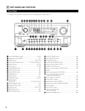
...!9 5CH/7CH STEREO button 69) @0 DSP SIMULATION button 69) @1 TONE DEFEAT button 50) @2 SURROUND PARAMETER button 59) @3 Channel Volume button (CH VOL 56) @4 MASTER VOLUME control 48) @5 Master volume indicator (VOLUME LEVEL ...48) @6 Display @7 Input mode indicators (INPUT MODE 48) @8 Surround speaker system indicators (SURROUND SPEAKER A/B 51) @9 Surround back ch indicators 61) #0 PURE DIRECT indicator 49) #1 Digital signal indicators (SIGNAL 48) #2 Remote control sensor (REMOTE...
...!9 5CH/7CH STEREO button 69) @0 DSP SIMULATION button 69) @1 TONE DEFEAT button 50) @2 SURROUND PARAMETER button 59) @3 Channel Volume button (CH VOL 56) @4 MASTER VOLUME control 48) @5 Master volume indicator (VOLUME LEVEL ...48) @6 Display @7 Input mode indicators (INPUT MODE 48) @8 Surround speaker system indicators (SURROUND SPEAKER A/B 51) @9 Surround back ch indicators 61) #0 PURE DIRECT indicator 49) #1 Digital signal indicators (SIGNAL 48) #2 Remote control sensor (REMOTE...
Owners Manual
Page 15
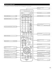
MULTI ZONE buttons 53) Mode selector buttons 34) Input source selectorbuttons.....(34~37, 47) Remote control signal transmitter 33) Power buttons 35, 46) MAIN ZONE buttons 53) Tuner system/System buttons 34, 37, 53, 73~75) BACK LIGHT button System ..., 61, 62, 69) Master volume control buttons 48, 53) MUTING button 51) SURROUND PARAMETER button 36, 59) CH SELECT/ENTER button 16, 36, 56) RETURN button 36) SURROUND SPEAKER/ SURROUND BACK button 51) INPUT MODE selector buttons 47, 49) 15 Remote control unit • For details on the functions of these parts, refer to...
MULTI ZONE buttons 53) Mode selector buttons 34) Input source selectorbuttons.....(34~37, 47) Remote control signal transmitter 33) Power buttons 35, 46) MAIN ZONE buttons 53) Tuner system/System buttons 34, 37, 53, 73~75) BACK LIGHT button System ..., 61, 62, 69) Master volume control buttons 48, 53) MUTING button 51) SURROUND PARAMETER button 36, 59) CH SELECT/ENTER button 16, 36, 56) RETURN button 36) SURROUND SPEAKER/ SURROUND BACK button 51) INPUT MODE selector buttons 47, 49) 15 Remote control unit • For details on the functions of these parts, refer to...
Owners Manual
Page 16
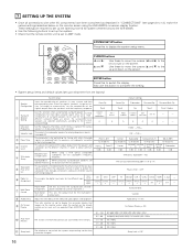
... Set this to switch the surround back channel's power amplifier for use this function when using the AVR-4802R's on the monitor screen using multiple surround speaker Surround combinations for multi-zone 2. Level...used for the DOLBY/ DTS SURROUND THX / THX 5.1 WIDE SCREEN 5CH/7CH DSP STEREO SIMULATION EXT. different surround modes are preset, the surround speakers are received automatically and stored in the memory... to lock the system setup settings so that the remote control unit is set up and down on the remote control unit or main unit are operated (from being...
... Set this to switch the surround back channel's power amplifier for use this function when using the AVR-4802R's on the monitor screen using multiple surround speaker Surround combinations for multi-zone 2. Level...used for the DOLBY/ DTS SURROUND THX / THX 5.1 WIDE SCREEN 5CH/7CH DSP STEREO SIMULATION EXT. different surround modes are preset, the surround speakers are received automatically and stored in the memory... to lock the system setup settings so that the remote control unit is set up and down on the remote control unit or main unit are operated (from being...

Owners Manual
Page 23
... 23 Sp." Sp.: B Adjusts the balance of the playback level between the channels when using surround speaker B. • Surr. Sp.: A+B Adjusts the balance of the playback level between the channels when using both surround speakers A and B, their playback levels can be selected when both A and ... adjusted separately. 1 At the System Setup Menu select "Channel Level". 2 Switch to adjust the level. • The level can also be adjusted directly from the remote control unit. (For details, see page 56.) • When using surround speaker A. • Surr. Select "Auto" or "...
... 23 Sp." Sp.: B Adjusts the balance of the playback level between the channels when using surround speaker B. • Surr. Sp.: A+B Adjusts the balance of the playback level between the channels when using both surround speakers A and B, their playback levels can be selected when both A and ... adjusted separately. 1 At the System Setup Menu select "Channel Level". 2 Switch to adjust the level. • The level can also be adjusted directly from the remote control unit. (For details, see page 56.) • When using surround speaker A. • Surr. Select "Auto" or "...

Owners Manual
Page 30
... default, this to turn the on or off. 1 At the System Setup Menu select "On Screen Display". 2 Switch to page 67. For instructions on the remote control unit. -40 dB, 0 dB: The output level is selected at the "Power Amp Assignment" setting. 3 Select "Multi Zone Vol. Adjusting the audio delay This...
... default, this to turn the on or off. 1 At the System Setup Menu select "On Screen Display". 2 Switch to page 67. For instructions on the remote control unit. -40 dB, 0 dB: The output level is selected at the "Power Amp Assignment" setting. 3 Select "Multi Zone Vol. Adjusting the audio delay This...
Owners Manual
Page 33
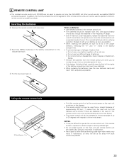
.... NOTES: • It may result in malfunction. • Neon signs or other remote control compatible DENON components as well. 8 REMOTE CONTROL UNIT • The included remote control unit (RC-932) can be used to operate not only the AVR-4802R but this depends on the frequency of usage. • Even if less than a ...year has passed, replace the batteries with new ones if the set does not operate even when the remote control unit is operated nearby the set as far ...
.... NOTES: • It may result in malfunction. • Neon signs or other remote control compatible DENON components as well. 8 REMOTE CONTROL UNIT • The included remote control unit (RC-932) can be used to operate not only the AVR-4802R but this depends on the frequency of usage. • Even if less than a ...year has passed, replace the batteries with new ones if the set does not operate even when the remote control unit is operated nearby the set as far ...
Owners Manual
Page 35
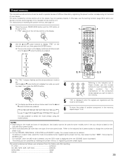
...want 4 to preset, then press the ENTER button. 4 2, 3 2, 3 1 2 3 4 5 6 7 8 9 0 Referring to the included List of Preset Codes, use more than one type of remote control code. For instructions on resetting the preset memory, see page 41. 1 Press the power ON/SOURCE button and the OFF button at the same...the signals are as follows upon shipment from the factory and after resetting: TV, VCR1 HITACHI CD, MD, TAPE, CDR, VDP, DVD DENON VCR2, DBS SONY CABLE ABC 35 Refer to the included list of another preset signal. The preset codes are registered and the mode is ...
...want 4 to preset, then press the ENTER button. 4 2, 3 2, 3 1 2 3 4 5 6 7 8 9 0 Referring to the included List of Preset Codes, use more than one type of remote control code. For instructions on resetting the preset memory, see page 41. 1 Press the power ON/SOURCE button and the OFF button at the same...the signals are as follows upon shipment from the factory and after resetting: TV, VCR1 HITACHI CD, MD, TAPE, CDR, VDP, DVD DENON VCR2, DBS SONY CABLE ABC 35 Refer to the included list of another preset signal. The preset codes are registered and the mode is ...
Owners Manual
Page 36
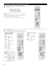
Some models cannot be operated with the remote control operation of track) 3 : Pause 0 ~ 9, +10 : 10 key DISC SKIP +: Disc skip (for the component you want to beginning of the various components. ... DVD (ON/SOURCE) OFF : Power off 6,7 : Manual search (forward and reverse) 2 : Stop 1 : Play 8,9 : Auto search (to operate. Compare with this remote control unit. 1. NOTE: • For the DVD player remote control buttons, function names may differ according to the component's operating instructions. Operating a component stored in the preset memory 1 Press the...
Some models cannot be operated with the remote control operation of track) 3 : Pause 0 ~ 9, +10 : 10 key DISC SKIP +: Disc skip (for the component you want to beginning of the various components. ... DVD (ON/SOURCE) OFF : Power off 6,7 : Manual search (forward and reverse) 2 : Stop 1 : Play 8,9 : Auto search (to operate. Compare with this remote control unit. 1. NOTE: • For the DVD player remote control buttons, function names may differ according to the component's operating instructions. Operating a component stored in the preset memory 1 Press the...
Owners Manual
Page 38
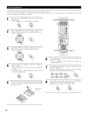
... unit 38 In such cases use the remote control unit included with the accessorious remote control unit by pressing a mode button while the "KEY" indicator is lit. Registering is not possible in the button on the other and press and hold in the receiver mode. Other keys can be "learned" ... units directly at each other remote control unit which you want to "learn ". 8 To cancel the learning mode, press the power ON/SOURCE button and the OFF button simultaneously again. Learning function If your AV component is not a Denon product or if it cannot be operated using the preset ...
... unit 38 In such cases use the remote control unit included with the accessorious remote control unit by pressing a mode button while the "KEY" indicator is lit. Registering is not possible in the button on the other and press and hold in the receiver mode. Other keys can be "learned" ... units directly at each other remote control unit which you want to "learn ". 8 To cancel the learning mode, press the power ON/SOURCE button and the OFF button simultaneously again. Learning function If your AV component is not a Denon product or if it cannot be operated using the preset ...

Owners Manual
Page 39
... for example to turn on the receiver's power, select the input source, turn on the monitor TV's power, turn the "KEY" indicator back on the remote control unit's display. 1 DVD 1 5 2, 3 3 Use the • and ª cursor buttons to display the name of remote control signals to be registered. 6...KEY" or "FULL" indicator is lit to register the signals at the system call button, then press the ENTER button. • Display "KEY" on the remote control unit's display. 7 2, 3, 5 5 The mode can be stored at the "CALL1" and "CALL2" buttons. (1) (2) Storing system call buttons Up ...
... for example to turn on the receiver's power, select the input source, turn on the monitor TV's power, turn the "KEY" indicator back on the remote control unit's display. 1 DVD 1 5 2, 3 3 Use the • and ª cursor buttons to display the name of remote control signals to be registered. 6...KEY" or "FULL" indicator is lit to register the signals at the system call button, then press the ENTER button. • Display "KEY" on the remote control unit's display. 7 2, 3, 5 5 The mode can be stored at the "CALL1" and "CALL2" buttons. (1) (2) Storing system call buttons Up ...
Owners Manual
Page 40
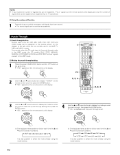
...170; cursor buttons are transmitted successively. NOTE: • If you exceed the number of signals that can be registered, "FULL" appears on the remote control unit's display and only the number of signals that can be registered are registered (up to select the mode directly using the mode buttons... call function 1 Press the button at the right which are pressed. Punch Through (1) Punch through is also possible to the buttons shown on the remote control unit's display. 4 Use the • and ª cursor buttons to display the mode you want to punch through, then press the ...
...170; cursor buttons are transmitted successively. NOTE: • If you exceed the number of signals that can be registered, "FULL" appears on the remote control unit's display and only the number of signals that can be registered are registered (up to select the mode directly using the mode buttons... call function 1 Press the button at the right which are pressed. Punch Through (1) Punch through is also possible to the buttons shown on the remote control unit's display. 4 Use the • and ª cursor buttons to display the mode you want to punch through, then press the ...

Owners Manual
Page 41
... unit's display. 2 Use the • and ª cursor buttons to display "BKLT" on the remote control unit, then press the ENTER button. • "05SEC" appears on the remote control unit's display. 3 Use the • and ª cursor buttons to adjust the lighting time (3 sec ~ 30 sec), then press the ENTER button. •... 1 DVD 1 2, 3 2, 3 Resetting (1) Resetting the preset memory 1 Press the power ON/SOURCE button and the OFF button at the same time. • "PRE" appears on the remote control unit's display. 2 Use the • and ª cursor buttons to display "RST" on the...
... unit's display. 2 Use the • and ª cursor buttons to display "BKLT" on the remote control unit, then press the ENTER button. • "05SEC" appears on the remote control unit's display. 3 Use the • and ª cursor buttons to adjust the lighting time (3 sec ~ 30 sec), then press the ENTER button. •... 1 DVD 1 2, 3 2, 3 Resetting (1) Resetting the preset memory 1 Press the power ON/SOURCE button and the OFF button at the same time. • "PRE" appears on the remote control unit's display. 2 Use the • and ª cursor buttons to display "RST" on the...
Owners Manual
Page 42
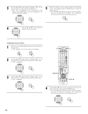
...power ON/SOURCE button and the OFF button at the same time. • "PRE" appears on the remote control unit's display. 2 Use the • and ª cursor buttons to display "RST" on the remote control unit's display, then press the ENTER button. • "PRE" is displayed. 1 DVD 1 3... Use the • and ª cursor buttons to display "LRN" on the remote control unit's display, then press the ENTER button. • "SEL" is displayed. 2, 3, 4 2, 3, 4 4 Use the • and ª cursor buttons to ...
...power ON/SOURCE button and the OFF button at the same time. • "PRE" appears on the remote control unit's display. 2 Use the • and ª cursor buttons to display "RST" on the remote control unit's display, then press the ENTER button. • "PRE" is displayed. 1 DVD 1 3... Use the • and ª cursor buttons to display "LRN" on the remote control unit's display, then press the ENTER button. • "SEL" is displayed. 2, 3, 4 2, 3, 4 4 Use the • and ª cursor buttons to ...


