Setup Guide
Page 25
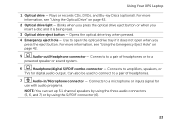
Using Your XPS Laptop 1 Optical drive - Connects to amplifiers, speakers, or TVs for use with audio programs. NOTE: You can set up 5.1 channel speakers by using the three audio connectors (5, 6, and 7) or by using the S/PDIF connector (6). 23 For more information, see "Using ...the Emergency Eject Hole" on page 42. 2 Optical drive light - Can also be used to connect to a pair of headphones or to a powered speaker or sound system. 6 Headphone/digital S/PDIF combo connector - Use to a pair of headphones. 7 Audio-in/Microphone connector - Blinks when you press the...
Using Your XPS Laptop 1 Optical drive - Connects to amplifiers, speakers, or TVs for use with audio programs. NOTE: You can set up 5.1 channel speakers by using the three audio connectors (5, 6, and 7) or by using the S/PDIF connector (6). 23 For more information, see "Using ...the Emergency Eject Hole" on page 42. 2 Optical drive light - Can also be used to connect to a pair of headphones or to a powered speaker or sound system. 6 Headphone/digital S/PDIF combo connector - Use to a pair of headphones. 7 Audio-in/Microphone connector - Blinks when you press the...
Setup Guide
Page 43
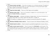
...Enable or Disable Wireless" on if the Caps Lock is enabled. 3 Wireless status light - Touch to launch the Dell Audio control panel. You can also change the audio settings such as volume, external speaker setup, and microphone setup. 41 For more information on the power button light, see "Status Lights and Indicators...-quality audio output on page 34. 2 Caps lock status light - The control panel allows you to launch a predefined application of your computer. Using Your XPS Laptop 1 Power button and light - NOTE: The battery is charging when the computer is enabled.
...Enable or Disable Wireless" on if the Caps Lock is enabled. 3 Wireless status light - Touch to launch the Dell Audio control panel. You can also change the audio settings such as volume, external speaker setup, and microphone setup. 41 For more information on the power button light, see "Status Lights and Indicators...-quality audio output on page 34. 2 Caps lock status light - The control panel allows you to launch a predefined application of your computer. Using Your XPS Laptop 1 Power button and light - NOTE: The battery is charging when the computer is enabled.

Setup Guide
Page 93
... DDR3 NOTE: For instructions on upgrading the memory, see the Service Manual at support.dell.com/manuals. Connectors Audio one microphone-in connector, one stereo headphones/speakers connector NOTE: You can also use the connectors to set up 5.1 channel speakers S/PDIF one headphone/digital S/PDIF combo connector Mini-Card one full Mini-Card...
... DDR3 NOTE: For instructions on upgrading the memory, see the Service Manual at support.dell.com/manuals. Connectors Audio one microphone-in connector, one stereo headphones/speakers connector NOTE: You can also use the connectors to set up 5.1 channel speakers S/PDIF one headphone/digital S/PDIF combo connector Mini-Card one full Mini-Card...

Setup Guide
Page 94
... Wireless WLAN, WWAN (optional), WiMAX/Wi-Fi abgn/agn, and Bluetooth® wireless technology (optional)/ WiDi (optional) TV TV tuner card (optional) Audio Audio controller Speakers Volume controls Realtek ALC665 2 x 1.5 Watt + 2.5 Watt software program menus and media controls
... Wireless WLAN, WWAN (optional), WiMAX/Wi-Fi abgn/agn, and Bluetooth® wireless technology (optional)/ WiDi (optional) TV TV tuner card (optional) Audio Audio controller Speakers Volume controls Realtek ALC665 2 x 1.5 Watt + 2.5 Watt software program menus and media controls

Service Manual
Page 7
Replacing the USB Board 88 20 TV Tuner Connector 91 Removing the TV Tuner Connector 91 Replacing the TV Tuner Connector 92 21 Heat Sink 95 Removing the Heat Sink 95 Replacing the Heat Sink 96 22 Processor Module 99 Removing the Processor Module 99 Replacing the Processor Module 101 23 System Board 103 Removing the System Board 103 Replacing the System Board 105 Entering the Service Tag in the BIOS 106 24 Speakers 109 Removing the Speakers 109 Replacing the Speakers 110 Contents 7
Replacing the USB Board 88 20 TV Tuner Connector 91 Removing the TV Tuner Connector 91 Replacing the TV Tuner Connector 92 21 Heat Sink 95 Removing the Heat Sink 95 Replacing the Heat Sink 96 22 Processor Module 99 Removing the Processor Module 99 Replacing the Processor Module 101 23 System Board 103 Removing the System Board 103 Replacing the System Board 105 Entering the Service Tag in the BIOS 106 24 Speakers 109 Removing the Speakers 109 Replacing the Speakers 110 Contents 7

Service Manual
Page 68
. 1 1 1 top-cover assembly 15 Remove heat sink (see "Removing the Heat Sink" on page 95). 16 Remove the system board (see "Removing the System Board" on page 103). 17 Remove the Bluetooth card (see "Removing the Bluetooth Card" on page 79). 18 Remove the AC-adapter connector (see "Removing the AC-Adapter Connector" on page 83). 19 Remove the USB board (see "Removing the USB Board" on page 87). 20 Remove the TV tuner connector (see "Removing the TV Tuner Connector" on page 91). 21 Remove the speakers (see "Removing the Speakers" on page 109). 68 Top Cover
. 1 1 1 top-cover assembly 15 Remove heat sink (see "Removing the Heat Sink" on page 95). 16 Remove the system board (see "Removing the System Board" on page 103). 17 Remove the Bluetooth card (see "Removing the Bluetooth Card" on page 79). 18 Remove the AC-adapter connector (see "Removing the AC-Adapter Connector" on page 83). 19 Remove the USB board (see "Removing the USB Board" on page 87). 20 Remove the TV tuner connector (see "Removing the TV Tuner Connector" on page 91). 21 Remove the speakers (see "Removing the Speakers" on page 109). 68 Top Cover

Service Manual
Page 69
Top Cover 69 Failure to do so may result in "Before You Begin" on page 9. 2 Replace the speakers (see "Replacing the Speakers" on page 110). 3 Replace the TV tuner connector (see "Replacing the TV Tuner Connector" on page 92). 4 Replace the USB board (see "Replacing the USB ...
Top Cover 69 Failure to do so may result in "Before You Begin" on page 9. 2 Replace the speakers (see "Replacing the Speakers" on page 110). 3 Replace the TV tuner connector (see "Replacing the TV Tuner Connector" on page 92). 4 Replace the USB board (see "Replacing the USB ...

Service Manual
Page 104
9 Disconnect the USB board cable and speaker cable from the connectors on the system board. 1 2 1 USB board cable connector 2 speaker cable connector 10 Turn the top cover over. 11 Remove the heat sink (see "Removing the Heat Sink" on page 95). 12 Remove the processor module (see "Removing the Processor Module" on page 99). 13 Disconnect the Bluetooth cable and AC-adapter cable from the connector on the system board. 14 Remove the five screws that secure the system board to the top cover. 104 System Board
9 Disconnect the USB board cable and speaker cable from the connectors on the system board. 1 2 1 USB board cable connector 2 speaker cable connector 10 Turn the top cover over. 11 Remove the heat sink (see "Removing the Heat Sink" on page 95). 12 Remove the processor module (see "Removing the Processor Module" on page 99). 13 Disconnect the Bluetooth cable and AC-adapter cable from the connector on the system board. 14 Remove the five screws that secure the system board to the top cover. 104 System Board

Service Manual
Page 106
... 101). 6 Replace the heat sink (see "Replacing the Heat Sink" on page 96). 7 Turn the top cover over and connect the USB board cable and speaker cable to the connector on the system board. 8 Follow the instructions from step 9 to step 12 in "Replacing the Top Cover" on page 69. 9 Replace...
... 101). 6 Replace the heat sink (see "Replacing the Heat Sink" on page 96). 7 Turn the top cover over and connect the USB board cable and speaker cable to the connector on the system board. 8 Follow the instructions from step 9 to step 12 in "Replacing the Top Cover" on page 69. 9 Replace...

Service Manual
Page 109
...: Only a certified service technician should perform repairs on your computer. Speakers 109 24 Speakers WARNING: Before working inside your computer, read the safety information that is not authorized by Dell™ is not covered by periodically touching an unpainted metal surface (...such as a connector on your computer). Removing the Speakers 1 Follow the instructions in "Before You Begin" on page 9. 2 Remove the system board (see the Regulatory Compliance Homepage at www.dell.com/regulatory_compliance. CAUTION: To avoid electrostatic discharge, ground yourself...
...: Only a certified service technician should perform repairs on your computer. Speakers 109 24 Speakers WARNING: Before working inside your computer, read the safety information that is not authorized by Dell™ is not covered by periodically touching an unpainted metal surface (...such as a connector on your computer). Removing the Speakers 1 Follow the instructions in "Before You Begin" on page 9. 2 Remove the system board (see the Regulatory Compliance Homepage at www.dell.com/regulatory_compliance. CAUTION: To avoid electrostatic discharge, ground yourself...
Service Manual
Page 110
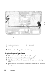
3 2 1 1 speaker cable routing 3 screws (4) 2 speakers (2) 5 Lift the speakers along with the screw holes on the top cover. 4 Replace the four screws (two on the speakers with its cable off the top cover. Replacing the Speakers 1 Follow the instructions in "Before You Begin" on page 9. 2 Route the speakers cable through the routing guides. 3 Align the screw holes on each speaker) that secure the speakers to the top cover. 110 Speakers
3 2 1 1 speaker cable routing 3 screws (4) 2 speakers (2) 5 Lift the speakers along with the screw holes on the top cover. 4 Replace the four screws (two on the speakers with its cable off the top cover. Replacing the Speakers 1 Follow the instructions in "Before You Begin" on page 9. 2 Route the speakers cable through the routing guides. 3 Align the screw holes on each speaker) that secure the speakers to the top cover. 110 Speakers

Service Manual
Page 111
5 Replace the system board (see "Replacing the System Board" on the computer, replace all screws and ensure that no stray screws remain inside the computer. CAUTION: Before turning on page 105). Speakers 111 Failure to do so may result in damage to the computer.
5 Replace the system board (see "Replacing the System Board" on the computer, replace all screws and ensure that no stray screws remain inside the computer. CAUTION: Before turning on page 105). Speakers 111 Failure to do so may result in damage to the computer.


