Setup Guide
Page 5
... Network Cable (Optional 9 Press the Power Button 10 Set Up Microsoft Windows 11 Create System Recovery Media (Recommended 12 Install the SIM Card (Optional 14 Enable or Disable Wireless (Optional 16 Set Up Wireless Display (Optional 18 Set Up the TV Tuner (Optional 19 Connect to the Internet (Optional 20 Using Your XPS Laptop 22 Right View Features 22 Left View Features 26 Front View Features 27 Back View Features 28 Computer Base and Keyboard Features 30 Status Lights and Indicators 34 Disabling Battery Charging...
... Network Cable (Optional 9 Press the Power Button 10 Set Up Microsoft Windows 11 Create System Recovery Media (Recommended 12 Install the SIM Card (Optional 14 Enable or Disable Wireless (Optional 16 Set Up Wireless Display (Optional 18 Set Up the TV Tuner (Optional 19 Connect to the Internet (Optional 20 Using Your XPS Laptop 22 Right View Features 22 Left View Features 26 Front View Features 27 Back View Features 28 Computer Base and Keyboard Features 30 Status Lights and Indicators 34 Disabling Battery Charging...
Setup Guide
Page 6
... Replacing the Battery 48 Software Features 50 Dell DataSafe Online Backup 51 Dell Stage (Optional 52 NVIDIA Optimus Technology 54 Free Fall Sensor 55 Dell Dock (Optional 56 Solving Problems 57 Beep Codes 57 Touch Screen Problems 58 Network Problems 59 Power Problems 60 Memory Problems 61 Lockups and Software Problems 62 Using Support Tools 64 Dell Support Center 64 My Dell Downloads 65 System Messages 65 Hardware Troubleshooter 67 Dell Diagnostics 67 Restoring Your Operating System 72 System Restore 73 Dell DataSafe Local Backup 74 System Recovery Media...
... Replacing the Battery 48 Software Features 50 Dell DataSafe Online Backup 51 Dell Stage (Optional 52 NVIDIA Optimus Technology 54 Free Fall Sensor 55 Dell Dock (Optional 56 Solving Problems 57 Beep Codes 57 Touch Screen Problems 58 Network Problems 59 Power Problems 60 Memory Problems 61 Lockups and Software Problems 62 Using Support Tools 64 Dell Support Center 64 My Dell Downloads 65 System Messages 65 Hardware Troubleshooter 67 Dell Diagnostics 67 Restoring Your Operating System 72 System Restore 73 Dell DataSafe Local Backup 74 System Recovery Media...
Setup Guide
Page 14
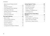
... changes to the hardware, software, drivers, or other system settings have left the computer in when you set up Microsoft Windows. You can be used to restore your computer to create the system recovery media: • Dell DataSafe Local Backup • USB key with a minimum capacity of the Operating System disc). You will require the following to the operating state it was in an undesirable operating state. Setting Up Your XPS Laptop Create System Recovery Media...
... changes to the hardware, software, drivers, or other system settings have left the computer in when you set up Microsoft Windows. You can be used to restore your computer to create the system recovery media: • Dell DataSafe Local Backup • USB key with a minimum capacity of the Operating System disc). You will require the following to the operating state it was in an undesirable operating state. Setting Up Your XPS Laptop Create System Recovery Media...
Setup Guide
Page 15
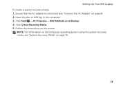
Ensure that the AC adapter is connected (see "System Recovery Media" on page 8). 2. Click Start → All Programs→ Dell DataSafe Local Backup. 4. NOTE: For information on restoring your operating system using the system recovery media, see "Connect the AC Adapter" on page 76. 13 Setting Up Your XPS Laptop To create a system recovery media: 1. Follow the instructions on the screen. Click Create Recovery Media. 5. Insert the disc or USB key in the computer. 3.
Ensure that the AC adapter is connected (see "System Recovery Media" on page 8). 2. Click Start → All Programs→ Dell DataSafe Local Backup. 4. NOTE: For information on restoring your operating system using the system recovery media, see "Connect the AC Adapter" on page 76. 13 Setting Up Your XPS Laptop To create a system recovery media: 1. Follow the instructions on the screen. Click Create Recovery Media. 5. Insert the disc or USB key in the computer. 3.
Setup Guide
Page 20
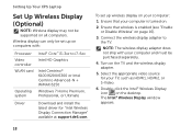
...; Wireless Display window appears. 18 Wireless display can only be set up on computers with your computer is enabled (see "Enable or Disable Wireless" on all computers. Double-click the Intel® Wireless Display icon on the TV and the wireless display adapter. 5. NOTE: The wireless display adapter does not ship with : Processor Video controller WLAN card Operating system Intel® Core™ i3-3xx to the TV. Setting Up Your XPS Laptop Set Up Wireless Display (Optional) NOTE: Wireless display...
...; Wireless Display window appears. 18 Wireless display can only be set up on computers with your computer is enabled (see "Enable or Disable Wireless" on all computers. Double-click the Intel® Wireless Display icon on the TV and the wireless display adapter. 5. NOTE: The wireless display adapter does not ship with : Processor Video controller WLAN card Operating system Intel® Core™ i3-3xx to the TV. Setting Up Your XPS Laptop Set Up Wireless Display (Optional) NOTE: Wireless display...
Setup Guide
Page 21
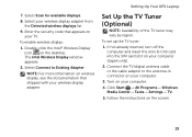
... (Japan only). 2. Turn on your computer. 4. Enter the security code that shipped with your computer. 3. Click Start → All Programs→ Windows Media Center→ Tasks→ Settings→ TV. 5. Double-click the Intel® Wireless Display icon on your wireless display adapter from the Detected wireless displays list. 9. To set up the TV tuner: 1. The Intel Wireless Display window appears. 2. 7. Select your TV. Follow the instructions on the screen. 19
... (Japan only). 2. Turn on your computer. 4. Enter the security code that shipped with your computer. 3. Click Start → All Programs→ Windows Media Center→ Tasks→ Settings→ TV. 5. Double-click the Intel® Wireless Display icon on your wireless display adapter from the Detected wireless displays list. 9. To set up the TV tuner: 1. The Intel Wireless Display window appears. 2. 7. Select your TV. Follow the instructions on the screen. 19
Setup Guide
Page 31
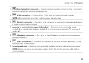
... 5.1 audio and video signals. Using Your XPS Laptop 1 Mini-DisplayPort connector - Connects to USB devices, such as a mouse, keyboard, printer, external drive, or MP3 player. 7 Security cable slot - Attaches a commercially available security cable to power the computer and charge the battery. 6 USB 3.0 connector - Connects to the AC adapter to the computer. NOTE: When used with a monitor, only the video signal is read. 3 Network connector - Digital interface standard connector that it fits into the security cable slot on supported models) - Connects...
... 5.1 audio and video signals. Using Your XPS Laptop 1 Mini-DisplayPort connector - Connects to USB devices, such as a mouse, keyboard, printer, external drive, or MP3 player. 7 Security cable slot - Attaches a commercially available security cable to power the computer and charge the battery. 6 USB 3.0 connector - Connects to the AC adapter to the computer. NOTE: When used with a monitor, only the video signal is read. 3 Network connector - Digital interface standard connector that it fits into the security cable slot on supported models) - Connects...
Setup Guide
Page 35
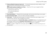
... a mouse. 8 Touch pad status light - To change the touch pad settings, double-click the Synaptics Pointing Device icon in the given order): • half keyboard brightness • full keyboard brightness • no lighting 7 Touch pad buttons - Provide left -click by illuminating all symbols on 33 The touch pad supports the Scroll, Flick, Zoom, and Rotate features. Turns on page 36. For more information, see "Touch Pad Gestures" on if the touch pad is disabled. 9 Touch pad - Backlit keyboard brightness settings - NOTE: To enable or disable...
... a mouse. 8 Touch pad status light - To change the touch pad settings, double-click the Synaptics Pointing Device icon in the given order): • half keyboard brightness • full keyboard brightness • no lighting 7 Touch pad buttons - Provide left -click by illuminating all symbols on 33 The touch pad supports the Scroll, Flick, Zoom, and Rotate features. Turns on page 36. For more information, see "Touch Pad Gestures" on if the touch pad is disabled. 9 Touch pad - Backlit keyboard brightness settings - NOTE: To enable or disable...
Setup Guide
Page 59
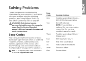
... Clock failure Video card or chip failure Processor failure Display failure 57 NOTE: To replace parts, see "Using Support Tools" on page 64 or "Contacting Dell" on page 87) for advanced service instructions. See the Service Manual at support.dell.com. Beep Codes Your computer might emit a series of beeps during start-up if there are errors or problems. This series of beeps, called a beep code, identifies a problem. BIOS ROM checksum failure No RAM detected...
... Clock failure Video card or chip failure Processor failure Display failure 57 NOTE: To replace parts, see "Using Support Tools" on page 64 or "Contacting Dell" on page 87) for advanced service instructions. See the Service Manual at support.dell.com. Beep Codes Your computer might emit a series of beeps during start-up if there are errors or problems. This series of beeps, called a beep code, identifies a problem. BIOS ROM checksum failure No RAM detected...
Setup Guide
Page 63
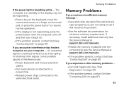
... a key on the keyboard, move the connected mouse or a finger on the touch pad, or press the power button to resume normal operation. • If the display is breathing white - Memory Problems If you receive an insufficient memory message - • Save and close any open files and exit any open programs you are : • Power, keyboard, and mouse extension cables. • Too many devices connected to a power strip. • Multiple power strips connected to...
... a key on the keyboard, move the connected mouse or a finger on the touch pad, or press the power button to resume normal operation. • If the display is breathing white - Memory Problems If you receive an insufficient memory message - • Save and close any open files and exit any open programs you are : • Power, keyboard, and mouse extension cables. • Too many devices connected to a power strip. • Multiple power strips connected to...
Setup Guide
Page 68
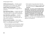
... hard drive, the hard drive cable is loose, or no bootable device exists. • If the hard drive is installed properly and partitioned as a boot device. • Enter system setup and ensure that a parameter has exceeded its normal operating range. S.M.A.R.T error, possible hard drive failure. Dell recommends that you back up your boot device, ensure that the cables are connected and that the drive is your data regularly. Using Support Tools CMOS checksum error - Replace the battery (see the Service Manual at support.dell...
... hard drive, the hard drive cable is loose, or no bootable device exists. • If the hard drive is installed properly and partitioned as a boot device. • Enter system setup and ensure that a parameter has exceeded its normal operating range. S.M.A.R.T error, possible hard drive failure. Dell recommends that you back up your boot device, ensure that the cables are connected and that the drive is your data regularly. Using Support Tools CMOS checksum error - Replace the battery (see the Service Manual at support.dell...
Setup Guide
Page 91
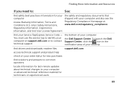
... drivers and downloads; find your desktop. Finding More Information and Resources If you need to: See: find safety best practices information for technicians or experienced users 89 only), Safety instructions, Regulatory information, Ergonomics information, and End User License Agreement the safety and regulatory documents that shipped with your computer review Warranty information, Terms and Conditions (U.S. readme files support.dell...
... drivers and downloads; find your desktop. Finding More Information and Resources If you need to: See: find safety best practices information for technicians or experienced users 89 only), Safety instructions, Regulatory information, Ergonomics information, and End User License Agreement the safety and regulatory documents that shipped with your computer review Warranty information, Terms and Conditions (U.S. readme files support.dell...
Setup Guide
Page 92
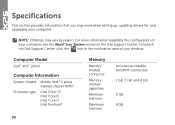
... setting up, updating drivers for, and upgrading your computer. For more information regarding the configuration of your computer, see the About Your System section in the Dell Support Center. To launch the Dell Support Center, click the icon in the notification area of your desktop. Computer Model Dell™ XPS™ L501X Computer Information System chipset Mobile Intel® 5 series express chipset HM57 Processor type...
... setting up, updating drivers for, and upgrading your computer. For more information regarding the configuration of your computer, see the About Your System section in the Dell Support Center. To launch the Dell Support Center, click the icon in the notification area of your desktop. Computer Model Dell™ XPS™ L501X Computer Information System chipset Mobile Intel® 5 series express chipset HM57 Processor type...

Service Manual
Page 3
Contents 1 Before You Begin 9 Recommended Tools 9 Turning Off Your Computer 9 Before Working Inside Your Computer 10 2 Battery 13 Removing the Battery 13 Replacing the Battery 14 3 Module Cover 15 Removing the Module Cover 15 Replacing the Module Cover 16 4 Memory Module(s 17 Removing the Memory Module(s 17 Replacing the Memory Module(s 18 5 Wireless Mini-Card(s 21 Removing the Mini-Card(s 21 Contents 3
Contents 1 Before You Begin 9 Recommended Tools 9 Turning Off Your Computer 9 Before Working Inside Your Computer 10 2 Battery 13 Removing the Battery 13 Replacing the Battery 14 3 Module Cover 15 Removing the Module Cover 15 Replacing the Module Cover 16 4 Memory Module(s 17 Removing the Memory Module(s 17 Replacing the Memory Module(s 18 5 Wireless Mini-Card(s 21 Removing the Mini-Card(s 21 Contents 3

Service Manual
Page 7
Replacing the USB Board 88 20 TV Tuner Connector 91 Removing the TV Tuner Connector 91 Replacing the TV Tuner Connector 92 21 Heat Sink 95 Removing the Heat Sink 95 Replacing the Heat Sink 96 22 Processor Module 99 Removing the Processor Module 99 Replacing the Processor Module 101 23 System Board 103 Removing the System Board 103 Replacing the System Board 105 Entering the Service Tag in the BIOS 106 24 Speakers 109 Removing the Speakers 109 Replacing the Speakers 110 Contents 7
Replacing the USB Board 88 20 TV Tuner Connector 91 Removing the TV Tuner Connector 91 Replacing the TV Tuner Connector 92 21 Heat Sink 95 Removing the Heat Sink 95 Replacing the Heat Sink 96 22 Processor Module 99 Removing the Processor Module 99 Replacing the Processor Module 101 23 System Board 103 Removing the System Board 103 Replacing the System Board 105 Entering the Service Tag in the BIOS 106 24 Speakers 109 Removing the Speakers 109 Replacing the Speakers 110 Contents 7
Service Manual
Page 24
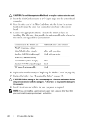
... black black 6 Replace the module cover (see "Replacing the Module Cover" on page 16). 7 Replace the battery (see "Replacing the Battery" on the computer, replace all screws and ensure that secures the Mini-Card to the system board. 5 Connect the appropriate antenna cables to the Mini-Card you are installing a communication card from a source other end of the Mini-Card down into the system-board connector. 4 Press the other than Dell, you are installing...
... black black 6 Replace the module cover (see "Replacing the Module Cover" on page 16). 7 Replace the battery (see "Replacing the Battery" on the computer, replace all screws and ensure that secures the Mini-Card to the system board. 5 Connect the appropriate antenna cables to the Mini-Card you are installing a communication card from a source other end of the Mini-Card down into the system-board connector. 4 Press the other than Dell, you are installing...

Service Manual
Page 65
... any installed cards from the Media Card Reader. 3 Remove the battery (see "Removing the Battery" on page 13). 4 Remove the module cover (see "Removing the Module Cover" on page 15). 5 Remove the memory module(s) (see "Removing the Memory Module(s)" on page 17). 6 Remove the palm-rest assembly (see "Removing the Palm-Rest Assembly" on page 29). 7 Remove the keyboard (see "Removing the Keyboard" on page 13) before working inside the computer. CAUTION: Only a certified service technician should perform repairs on...
... any installed cards from the Media Card Reader. 3 Remove the battery (see "Removing the Battery" on page 13). 4 Remove the module cover (see "Removing the Module Cover" on page 15). 5 Remove the memory module(s) (see "Removing the Memory Module(s)" on page 17). 6 Remove the palm-rest assembly (see "Removing the Palm-Rest Assembly" on page 29). 7 Remove the keyboard (see "Removing the Keyboard" on page 13) before working inside the computer. CAUTION: Only a certified service technician should perform repairs on...

Service Manual
Page 69
... display assembly (see "Replacing the Display Assembly" on page 52). 14 Replace the keyboard (see "Replacing the Keyboard" on page 46). 15 Replace the palm-rest assembly (see "Replacing the Palm-Rest Assembly" on page 32). 16 Replace the memory module(s) (see "Replacing the Memory Module(s)" on page 18). 17 Replace the module cover (see "Replacing the Module Cover" on page 16). 18 Replace any blank or card you removed from the Media Card Reader. 19 Replace the battery...
... display assembly (see "Replacing the Display Assembly" on page 52). 14 Replace the keyboard (see "Replacing the Keyboard" on page 46). 15 Replace the palm-rest assembly (see "Replacing the Palm-Rest Assembly" on page 32). 16 Replace the memory module(s) (see "Replacing the Memory Module(s)" on page 18). 17 Replace the module cover (see "Replacing the Module Cover" on page 16). 18 Replace any blank or card you removed from the Media Card Reader. 19 Replace the battery...

Service Manual
Page 79
... instructions in "Removing the Top Cover" on page 65. 9 Turn the top-cover assembly over. CAUTION: Only a certified service technician should perform repairs on your computer). Damage due to servicing that shipped with your warranty. CAUTION: To avoid electrostatic discharge, ground yourself by using a wrist grounding strap or by your computer. Internal Card With Bluetooth Wireless Technology 79 17 Internal Card With Bluetooth Wireless Technology WARNING: Before working...
... instructions in "Removing the Top Cover" on page 65. 9 Turn the top-cover assembly over. CAUTION: Only a certified service technician should perform repairs on your computer). Damage due to servicing that shipped with your warranty. CAUTION: To avoid electrostatic discharge, ground yourself by using a wrist grounding strap or by your computer. Internal Card With Bluetooth Wireless Technology 79 17 Internal Card With Bluetooth Wireless Technology WARNING: Before working...

Service Manual
Page 106
... cover over and connect the USB board cable and speaker cable to the connector on the system board. 8 Follow the instructions from step 9 to the computer. 15 Turn on the computer. NOTE: After you have replaced the system board, enter the computer Service Tag into the BIOS of the replacement system board. 16 Enter the service tag (see "Replacing the Battery" on the computer. 3 Press during POST to enter the system setup...
... cover over and connect the USB board cable and speaker cable to the connector on the system board. 8 Follow the instructions from step 9 to the computer. 15 Turn on the computer. NOTE: After you have replaced the system board, enter the computer Service Tag into the BIOS of the replacement system board. 16 Enter the service tag (see "Replacing the Battery" on the computer. 3 Press during POST to enter the system setup...


