Owner's Manual
Page 131
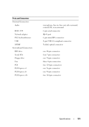
... 1394 Network adapter PS/2 keyboard/mouse USB S/PDIF Systemboard Connectors IDE drive Serial ATA Floppy drive Fan PCI PCI Express x1 PCI Express x8 PCI Express x16 microphone, line-in, line-out, side-surround, center/LFE, rear-surround 6-pin serial connector RJ-45 port 6-pin mini-DIN connector 4-pin USB 2.0-compliant connector...
... 1394 Network adapter PS/2 keyboard/mouse USB S/PDIF Systemboard Connectors IDE drive Serial ATA Floppy drive Fan PCI PCI Express x1 PCI Express x8 PCI Express x16 microphone, line-in, line-out, side-surround, center/LFE, rear-surround 6-pin serial connector RJ-45 port 6-pin mini-DIN connector 4-pin USB 2.0-compliant connector...
Service Manual
Page 102
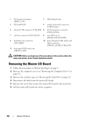
... 4 media card reader connector (USB_Flexbay) 5 internal USB connector (USB_MB) 6 I/O board power connector (PWR_CONN) 7 card fan connector (FAN_CCAG) 8 rear LED sensor (REAR_LED_SENSOR) 9 hard drive fan connector (FAN_HDD) 10 front I/O panel USB, audio, and lights connector (FRONT_AUDIO_USB_LED) 11 front panel LED connector (FRONT_LED) CAUTION...page 9. 2 Remove the computer cover (see "Removing the Computer Cover" on page 13). 3 Remove the card fan cage (see "Removing the Card Fan" on page 69). 4 Disconnect all cables from the master I/O board. 5 Remove the screw that secures the master...
... 4 media card reader connector (USB_Flexbay) 5 internal USB connector (USB_MB) 6 I/O board power connector (PWR_CONN) 7 card fan connector (FAN_CCAG) 8 rear LED sensor (REAR_LED_SENSOR) 9 hard drive fan connector (FAN_HDD) 10 front I/O panel USB, audio, and lights connector (FRONT_AUDIO_USB_LED) 11 front panel LED connector (FRONT_LED) CAUTION...page 9. 2 Remove the computer cover (see "Removing the Computer Cover" on page 13). 3 Remove the card fan cage (see "Removing the Card Fan" on page 69). 4 Disconnect all cables from the master I/O board. 5 Remove the screw that secures the master...


