Setup and Quick Reference Guide
Page 7
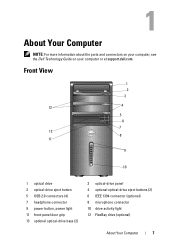
Front View 1 2 3 13 4 5 6 7 12 8 11 9 10 1 optical drive 3 optical-drive eject button 5 USB 2.0 connectors (4) 7 headphone connector 9 power button, power light 11 front-panel door grip 13 optional optical-drive bays (2) 2 optical-drive panel 4 optional optical-drive eject buttons (2) 6 IEEE 1394 connector (optional) 8 microphone connector 10 drive activity light 12 FlexBay drive (optional) About Your Computer 7 About Your Computer NOTE: For more information about the ports and connectors on your computer, see the Dell Technology Guide on your computer or at support.dell.com.
Front View 1 2 3 13 4 5 6 7 12 8 11 9 10 1 optical drive 3 optical-drive eject button 5 USB 2.0 connectors (4) 7 headphone connector 9 power button, power light 11 front-panel door grip 13 optional optical-drive bays (2) 2 optical-drive panel 4 optional optical-drive eject buttons (2) 6 IEEE 1394 connector (optional) 8 microphone connector 10 drive activity light 12 FlexBay drive (optional) About Your Computer 7 About Your Computer NOTE: For more information about the ports and connectors on your computer, see the Dell Technology Guide on your computer or at support.dell.com.
Service Manual
Page 14
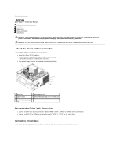
... optional Floppy Drive or optional Media Card Reader (FlexBay) 1 drive bay 2 optional optical drive 3 optional drive 4 optional FlexBay (Floppy Drive or Media Card Reader) 5 3.5-inch SATA drive bays (4) Recommended Drive Cable Connections l Connect serial ATA hard drives to connectors labeled "SATA0," "SATA1," "SATA2," or "SATA3" on the system board. CAUTION: To guard against electrical shock, always unplug your computer. Back to Contents Page Drives Dell™ Vostro™ 410 Service...
... optional Floppy Drive or optional Media Card Reader (FlexBay) 1 drive bay 2 optional optical drive 3 optional drive 4 optional FlexBay (Floppy Drive or Media Card Reader) 5 3.5-inch SATA drive bays (4) Recommended Drive Cable Connections l Connect serial ATA hard drives to connectors labeled "SATA0," "SATA1," "SATA2," or "SATA3" on the system board. CAUTION: To guard against electrical shock, always unplug your computer. Back to Contents Page Drives Dell™ Vostro™ 410 Service...
Service Manual
Page 23
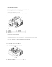
...for drive operation. 12. Gently slide the optical drive into place. 5. Removing the Optical Panel Insert Release the optical panel insert by running Dell Diagnostics. Replace the bezel (see Entering System Setup). 13. Align the screw slots in the optical drive with the drive ...Perform the steps in the optical drive bay. 6. See your computer works correctly by pushing it out of the chassis. 1 optical panel insert (optional) Replace and tighten the two screws securing the optical drive. 7. Enter system setup and select the appropriate Drive option (see Replacing the Bezel...
...for drive operation. 12. Gently slide the optical drive into place. 5. Removing the Optical Panel Insert Release the optical panel insert by running Dell Diagnostics. Replace the bezel (see Entering System Setup). 13. Align the screw slots in the optical drive with the drive ...Perform the steps in the optical drive bay. 6. See your computer works correctly by pushing it out of the chassis. 1 optical panel insert (optional) Replace and tighten the two screws securing the optical drive. 7. Enter system setup and select the appropriate Drive option (see Replacing the Bezel...
Service Manual
Page 61
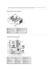
... for about 4 seconds to turn them off . Ensure that the computer and all attached devices are turned off . Inside View of Your Computer 1 power supply 3 optional optical drive bays 5 USB, audio, 1394 (optional) connectors 7 chassis fan ` 2 optical drive bay 4 floppy drive or Media Reader (optional) 6 3.5-inch drive bays (4) System Board Components 1 power connector (PWR2) 2 CPU fan power 4 main power connector (PWR1) 5 floppy...
... for about 4 seconds to turn them off . Ensure that the computer and all attached devices are turned off . Inside View of Your Computer 1 power supply 3 optional optical drive bays 5 USB, audio, 1394 (optional) connectors 7 chassis fan ` 2 optical drive bay 4 floppy drive or Media Reader (optional) 6 3.5-inch drive bays (4) System Board Components 1 power connector (PWR2) 2 CPU fan power 4 main power connector (PWR1) 5 floppy...


