
User Manual
Page 1
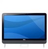
Front View 1. camera 3. optical-drive eject button 8. drive activity light 9. power button 10. camera privacy cover 2. camera activity light 4. microphone 5. display 6. stand Regulatory Model : W03C Regulatory Type : W03C001 2011 - 05 optical drive 7. Dell Vostro 360 Setup And Features Information About Warnings WARNING: A WARNING indicates a potential for property damage, personal injury, or death. Front View Figure 1.
Front View 1. camera 3. optical-drive eject button 8. drive activity light 9. power button 10. camera privacy cover 2. camera activity light 4. microphone 5. display 6. stand Regulatory Model : W03C Regulatory Type : W03C001 2011 - 05 optical drive 7. Dell Vostro 360 Setup And Features Information About Warnings WARNING: A WARNING indicates a potential for property damage, personal injury, or death. Front View Figure 1.
User Manual
Page 2
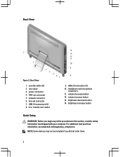
... section, read the safety information that shipped with your computer. volume decrease button 12. For additional best practices information, see www.dell.com/regulatory_compliance. Back View Figure 2. power connector 4. network connector 6. brightness decrease button 14. NOTE: Some devices may not be... included if you begin any of the procedures in -1 media card reader 9. rear stand 3. line-out connector 7. Back View 1. VGA-out connector 5. USB 2.0 connectors (2) 10. brightness increase button Quick Setup WARNING: Before ...
... section, read the safety information that shipped with your computer. volume decrease button 12. For additional best practices information, see www.dell.com/regulatory_compliance. Back View Figure 2. power connector 4. network connector 6. brightness decrease button 14. NOTE: Some devices may not be... included if you begin any of the procedures in -1 media card reader 9. rear stand 3. line-out connector 7. Back View 1. VGA-out connector 5. USB 2.0 connectors (2) 10. brightness increase button Quick Setup WARNING: Before ...
User Manual
Page 3
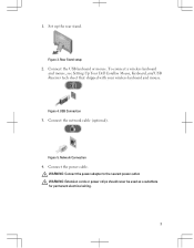
Connect the network cable (optional). Connect the power cable. Figure 5. USB Connection 3. Network Connection 4. To connect a wireless keyboard and mouse, see Setting Up Your Dell Cordless Mouse, Keyboard, and USB Receiver tech sheet that shipped with your wireless keyboard and mouse. WARNING: Connect the power adapter to the nearest power outlet. Rear Stand setup 2. Connect the USB keyboard or mouse. Figure 3. Figure 4. WARNING: Extension cords or power strips should never be used as a substitute for permanent electrical wiring. 3 1. Set up the rear stand.
Connect the network cable (optional). Connect the power cable. Figure 5. USB Connection 3. Network Connection 4. To connect a wireless keyboard and mouse, see Setting Up Your Dell Cordless Mouse, Keyboard, and USB Receiver tech sheet that shipped with your wireless keyboard and mouse. WARNING: Connect the power adapter to the nearest power outlet. Rear Stand setup 2. Connect the USB keyboard or mouse. Figure 3. Figure 4. WARNING: Extension cords or power strips should never be used as a substitute for permanent electrical wiring. 3 1. Set up the rear stand.


