Setup and Features Information Tech Sheet
Page 1
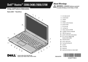
... (VGA) 10 e-SATA connector (shared) 11 USB 2.0 connector 12 power and battery status lights 13 5-in-1 Secure Digital (SD) memory card reader 14 wireless switch 15 audio connectors 16 touchpad buttons (2) 17 speaker 18 touchpad 19 keyboard 20 keyboard and device status lights Regulatory...FILE LOCATION: C:\Documents and Settings\kandasamy_m\Desktop\Winery_A01\Info Dev Template Last Updated - 01/02/2008 January 2010 Dell™ Vostro™ 3300/3400/3500/3700 Setup and Features Information About Warnings WARNING: A WARNING indicates a potential for property damage, personal injury, or death...
... (VGA) 10 e-SATA connector (shared) 11 USB 2.0 connector 12 power and battery status lights 13 5-in-1 Secure Digital (SD) memory card reader 14 wireless switch 15 audio connectors 16 touchpad buttons (2) 17 speaker 18 touchpad 19 keyboard 20 keyboard and device status lights Regulatory...FILE LOCATION: C:\Documents and Settings\kandasamy_m\Desktop\Winery_A01\Info Dev Template Last Updated - 01/02/2008 January 2010 Dell™ Vostro™ 3300/3400/3500/3700 Setup and Features Information About Warnings WARNING: A WARNING indicates a potential for property damage, personal injury, or death...
Setup and Features Information Tech Sheet
Page 3
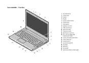
Vostro 3400/3500 - Front View 21 1 2 3 4 20 19 18 17 16 15 14 10 11 12 13 5 6 7 8 9 FILE LOCATION: C:\Documents and Settings\kandasamy_m\Desktop\Winery_A01\Info Dev 1 microphones (2) 2 ... control buttons 6 power button 7 right speaker 8 network connector 9 USB 2.0 connector 10 optical drive/bay 11 fingerprint reader 12 ExpressCard connector 13 8-in-1 Secure Digital (SD) memory card reader 14 power and battery status lights 15 audio connectors 16 wireless switch 17 touchpad buttons (2) 18 touchpad 19 keyboard 20 left speaker 21...
Vostro 3400/3500 - Front View 21 1 2 3 4 20 19 18 17 16 15 14 10 11 12 13 5 6 7 8 9 FILE LOCATION: C:\Documents and Settings\kandasamy_m\Desktop\Winery_A01\Info Dev 1 microphones (2) 2 ... control buttons 6 power button 7 right speaker 8 network connector 9 USB 2.0 connector 10 optical drive/bay 11 fingerprint reader 12 ExpressCard connector 13 8-in-1 Secure Digital (SD) memory card reader 14 power and battery status lights 15 audio connectors 16 wireless switch 17 touchpad buttons (2) 18 touchpad 19 keyboard 20 left speaker 21...
Setup and Features Information Tech Sheet
Page 5
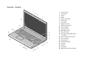
... 7 right speaker 8 network connector 9 USB 2.0 connectors (2) 10 optical drive/bay 11 fingerprint reader 12 IEEE 1394 connector 13 ExpressCard slot 14 8-in-1 Secure Digital (SD) memory card reader 15 power and battery status lights 16 audio connectors 17 wireless switch 18 touchpad buttons (2) 19 touchpad 20 keyboard 21 left speaker 22...
... 7 right speaker 8 network connector 9 USB 2.0 connectors (2) 10 optical drive/bay 11 fingerprint reader 12 IEEE 1394 connector 13 ExpressCard slot 14 8-in-1 Secure Digital (SD) memory card reader 15 power and battery status lights 16 audio connectors 17 wireless switch 18 touchpad buttons (2) 19 touchpad 20 keyboard 21 left speaker 22...
Setup and Features Information Tech Sheet
Page 8
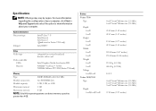
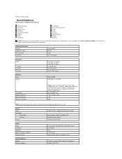
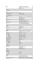
...Module connectors two SODIMM slots Module capacity 1 GB, 2 GB, or 4 GB Minimum memory 1 GB Maximum memory 8 GB NOTE: Only 64-bit operating systems can detect memory capacities greater than 4 GB. Battery Vostro 3300 Type Depth 4-cell 8-cell Height 4-cell 8-cell Width 4-cell 8-cell Weight ...4-cell 8-cell Voltage 4-cell/8-cell Vostro 3400/3500 Type Depth 4-cell/6-cell/9-cell FILE LOCATION: C:\Documents and ...
...Module connectors two SODIMM slots Module capacity 1 GB, 2 GB, or 4 GB Minimum memory 1 GB Maximum memory 8 GB NOTE: Only 64-bit operating systems can detect memory capacities greater than 4 GB. Battery Vostro 3300 Type Depth 4-cell 8-cell Height 4-cell 8-cell Width 4-cell 8-cell Weight ...4-cell 8-cell Voltage 4-cell/8-cell Vostro 3400/3500 Type Depth 4-cell/6-cell/9-cell FILE LOCATION: C:\Documents and ...
Service Manual
Page 9
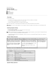
... > and < Right Arrow > keys to access the System Setup options. Select the sub menu or execute command. Back to Contents Page System Setup Dell™ Vostro™ 3500 Service Manual Overview Entering System Setup System Setup Screens System Setup Options Overview Use System Setup as follows: l To change the system configuration information...Options Field are an expert computer user, do not change a user-selectable option such as the user password l To read the current amount of memory or set the type of the System Setup window and contains help information about your computer. 2.
... > and < Right Arrow > keys to access the System Setup options. Select the sub menu or execute command. Back to Contents Page System Setup Dell™ Vostro™ 3500 Service Manual Overview Entering System Setup System Setup Screens System Setup Options Overview Use System Setup as follows: l To change the system configuration information...Options Field are an expert computer user, do not change a user-selectable option such as the user password l To read the current amount of memory or set the type of the System Setup window and contains help information about your computer. 2.
Service Manual
Page 10
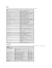
...Dell Bios Version Name System Date System Time Processor Type Processor Cores Processor ID Processor Speed Processor Minimum Clock Speed Processor Maximum Clock Speed L2 Cache Size L3 Cache Size System Memory Memory Speed Memory Channel Mode DIMM A Size DIMM B Size Internal HDD Fixed Bay Device Video Controller Video BIOS Version Video Memory...Default: Enabled Default: Hybrid Performance Displays the BIOS revision. Displays the processor L3 cache size. Displays the video memory size. Displays the type of each option. The table below defines the function of the computer. Enable or ...
...Dell Bios Version Name System Date System Time Processor Type Processor Cores Processor ID Processor Speed Processor Minimum Clock Speed Processor Maximum Clock Speed L2 Cache Size L3 Cache Size System Memory Memory Speed Memory Channel Mode DIMM A Size DIMM B Size Internal HDD Fixed Bay Device Video Controller Video BIOS Version Video Memory...Default: Enabled Default: Hybrid Performance Displays the BIOS revision. Displays the processor L3 cache size. Displays the video memory size. Displays the type of each option. The table below defines the function of the computer. Enable or ...
Service Manual
Page 17
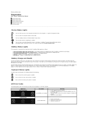
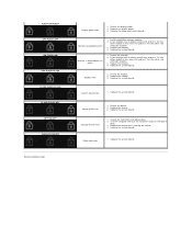
...lights appear, the battery is already present, reseat the module(s) one at least 3 seconds. Each light represents incremental degradation. If memory is in full charge mode with AC adapter present. l Constantly blinking amber light - Replace the system board. 3. Turns on...the processor. Fatal battery failure with Bluetooth® wireless technology is enabled. Install supported memory modules. 2. Back to Contents Page Diagnostics Dell™ Vostro™ 3500 Service Manual Device Status Lights Battery Status Lights Battery Charge and Health Keyboard Status Lights ...
...lights appear, the battery is already present, reseat the module(s) one at least 3 seconds. Each light represents incremental degradation. If memory is in full charge mode with AC adapter present. l Constantly blinking amber light - Replace the system board. 3. Turns on...the processor. Fatal battery failure with Bluetooth® wireless technology is enabled. Install supported memory modules. 2. Back to Contents Page Diagnostics Dell™ Vostro™ 3500 Service Manual Device Status Lights Battery Status Lights Battery Charge and Health Keyboard Status Lights ...
Service Manual
Page 18
...OFF OFF-ON-OFF FLASH-FLASH-ON Back to Contents Page Display panel error 1. Replace the video card/system board. Install compatible memory modules. 2. Replace the memory. 4. Try the other slot with both modules. 3. Option ROM error 1. Test the computer with both modules. 3. Video card ... Reseat the device. 2. Replace the system board. If two modules are installed, remove one and test. Reseat the display cable. 2. Memory compatibility error 1. Try the other slot with just the hard drive and just the optical drive. 3. Test the other module in the...
...OFF OFF-ON-OFF FLASH-FLASH-ON Back to Contents Page Display panel error 1. Replace the video card/system board. Install compatible memory modules. 2. Replace the memory. 4. Try the other slot with both modules. 3. Option ROM error 1. Test the computer with both modules. 3. Video card ... Reseat the device. 2. Replace the system board. If two modules are installed, remove one and test. Reseat the display cable. 2. Memory compatibility error 1. Try the other slot with just the hard drive and just the optical drive. 3. Test the other module in the...
Service Manual
Page 43
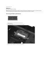
Remove the battery. 3. Back to release the memory module. 5. Push apart the memory retention clips to Contents Page Memory Dell™ Vostro™ 3500 Service Manual WARNING: Before working inside your computer, read the safety information that shipped with your computer. Remove the base cover. 4. For additional safety best ...
Remove the battery. 3. Back to release the memory module. 5. Push apart the memory retention clips to Contents Page Memory Dell™ Vostro™ 3500 Service Manual WARNING: Before working inside your computer, read the safety information that shipped with your computer. Remove the base cover. 4. For additional safety best ...

Service Manual
Page 44
Back to Contents Page Replacing the Memory Module(s) To replace the memory module(s), perform the above steps in reverse order.
Back to Contents Page Replacing the Memory Module(s) To replace the memory module(s), perform the above steps in reverse order.
Service Manual
Page 45
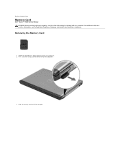
Back to release it from the computer. 3. Slide the memory card out of the computer. Press in Before Working Inside Your Computer. 2. Removing the Memory Card 1. For additional safety best practices information, see the Regulatory Compliance Homepage at www.dell.com/regulatory_compliance. Follow the procedures in on the memory card to Contents Page Memory Card Dell™ Vostro™ 3500 Service Manual WARNING: Before working inside your computer, read the safety information that shipped with your computer.
Back to release it from the computer. 3. Slide the memory card out of the computer. Press in Before Working Inside Your Computer. 2. Removing the Memory Card 1. For additional safety best practices information, see the Regulatory Compliance Homepage at www.dell.com/regulatory_compliance. Follow the procedures in on the memory card to Contents Page Memory Card Dell™ Vostro™ 3500 Service Manual WARNING: Before working inside your computer, read the safety information that shipped with your computer.

Service Manual
Page 46
Back to Contents Page Replacing the Memory Card To replace the memory card, perform the above steps in reverse order.
Back to Contents Page Replacing the Memory Card To replace the memory card, perform the above steps in reverse order.
Service Manual
Page 56
Back to Contents Page Removing and Replacing Parts Dell™ Vostro™ 3500 Service Manual Battery ExpressCard Base Cover Hard Drive Coin-Cell Battery Wireless Local Area Network (WLAN) Card Palm Rest Bluetooth Card Speaker Display Bezel Camera Heat Sink System Board Memory Card Subscriber Identity Module (SIM) Card Memory Optical Drive Wireless Wide Area Network (WWAN) Card Keyboard Audio Board Power-Button Board Display Assembly Display Panel ExpressCard Cage Processor I/O Board Back to Contents Page
Back to Contents Page Removing and Replacing Parts Dell™ Vostro™ 3500 Service Manual Battery ExpressCard Base Cover Hard Drive Coin-Cell Battery Wireless Local Area Network (WLAN) Card Palm Rest Bluetooth Card Speaker Display Bezel Camera Heat Sink System Board Memory Card Subscriber Identity Module (SIM) Card Memory Optical Drive Wireless Wide Area Network (WWAN) Card Keyboard Audio Board Power-Button Board Display Assembly Display Panel ExpressCard Cage Processor I/O Board Back to Contents Page
Service Manual
Page 68
... Module capacities Minimum memory Maximum memory NOTE: Intel Core i3/i5/i7 dual-core processors shipped with your computer, click Start® Help and Support and select the option to Contents Page Specifications Dell™ Vostro™ 3500 Service Manual Communications ...Processor ExpressCard Keyboard System Information Battery Audio Touchpad AC Adapter Ports and Connectors Drives Video Physical Environmental Display Memory NOTE: Offerings may vary by region.
... Module capacities Minimum memory Maximum memory NOTE: Intel Core i3/i5/i7 dual-core processors shipped with your computer, click Start® Help and Support and select the option to Contents Page Specifications Dell™ Vostro™ 3500 Service Manual Communications ...Processor ExpressCard Keyboard System Information Battery Audio Touchpad AC Adapter Ports and Connectors Drives Video Physical Environmental Display Memory NOTE: Offerings may vary by region.
Service Manual
Page 69
..., stereo headphone/speakers connector 15-pin VGA connector 19-pin HDMI connector RJ-45 connector three USB 2.0-compliant connectors one eSATA/USB 2.0-compliant connector 8-in-1 memory card reader PCI-E half-mini card support for WLAN PCI-E full-mini card support for WWAN PCI-E 6250 half-mini card support for microwave access...
..., stereo headphone/speakers connector 15-pin VGA connector 19-pin HDMI connector RJ-45 connector three USB 2.0-compliant connectors one eSATA/USB 2.0-compliant connector 8-in-1 memory card reader PCI-E half-mini card support for WLAN PCI-E full-mini card support for WWAN PCI-E 6250 half-mini card support for microwave access...
Service Manual
Page 72
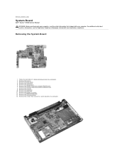
Back to the computer. Remove the battery. 3. Remove the keyboard. 10. Remove the memory. 9. Remove the base cover. 4. Follow the procedures in Before Working Inside Your Computer. 2. Remove the hard drive. 5. Remove the coin-... 8. Remove the screws that shipped with your computer, read the safety information that secure the system board to Contents Page System Board Dell™ Vostro™ 3500 Service Manual WARNING: Before working inside your computer. Removing the System Board 1. For additional safety best practices information, see the Regulatory ...
Back to the computer. Remove the battery. 3. Remove the keyboard. 10. Remove the memory. 9. Remove the base cover. 4. Follow the procedures in Before Working Inside Your Computer. 2. Remove the hard drive. 5. Remove the coin-... 8. Remove the screws that shipped with your computer, read the safety information that secure the system board to Contents Page System Board Dell™ Vostro™ 3500 Service Manual WARNING: Before working inside your computer. Removing the System Board 1. For additional safety best practices information, see the Regulatory ...


