Owner's Manual
Page 3
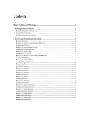
... Network (WLAN) Card 11 Installing the WLAN Card...11 Removing the Coin-Cell Battery...11 Installing the Coin-Cell Battery...12 Removing the Memory...12 Installing the Memory...12 Removing the Keyboard...12 Installing the Keyboard...14 Removing the Palmrest...14 Installing the Palmrest...17 Removing the Battery...18 Installing the Battery...
... Network (WLAN) Card 11 Installing the WLAN Card...11 Removing the Coin-Cell Battery...11 Installing the Coin-Cell Battery...12 Removing the Memory...12 Installing the Memory...12 Removing the Keyboard...12 Installing the Keyboard...14 Removing the Palmrest...14 Installing the Palmrest...17 Removing the Battery...18 Installing the Battery...
Owner's Manual
Page 12
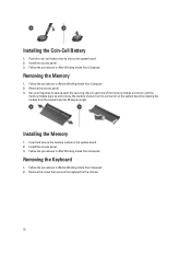
Follow the procedures in Before Working Inside Your Computer. 2. Insert and secure the memory module to the chassis. 12 Follow the procedures in Before Working Inside Your Computer. 2. Follow the procedures in After Working Inside Your Computer. Remove the ... Your Computer. Install the access panel. 3. Use your fingertips to spread apart the securing clips on each end of the memory module connector until the memory module pops up and remove the memory module from its slot on the system board by drawing the module from the system board at 45-degree angle...
Follow the procedures in Before Working Inside Your Computer. 2. Insert and secure the memory module to the chassis. 12 Follow the procedures in Before Working Inside Your Computer. 2. Follow the procedures in After Working Inside Your Computer. Remove the ... Your Computer. Install the access panel. 3. Use your fingertips to spread apart the securing clips on each end of the memory module connector until the memory module pops up and remove the memory module from its slot on the system board by drawing the module from the system board at 45-degree angle...
Owner's Manual
Page 39
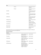
Main Fixed HDD SATA ODD mSata Device AC Adapter Type Extended Memory System Memory Memory Speed Keyboard Type L2 Cache L3 Cache Displays the processor L2 cache size. Displays the memory installed on the computer. Displays the memory speed. USB Emulation Enable or disable the USB Default: Enabled ...Displays the model number and capacity of the miniSata device. Displays the model number and capacity of the hard drive. Displays the memory in-built on the computer. This feature is enabled only when the AC adapter is connected. The table below defines the function...
Main Fixed HDD SATA ODD mSata Device AC Adapter Type Extended Memory System Memory Memory Speed Keyboard Type L2 Cache L3 Cache Displays the processor L2 cache size. Displays the memory installed on the computer. Displays the memory speed. USB Emulation Enable or disable the USB Default: Enabled ...Displays the model number and capacity of the miniSata device. Displays the model number and capacity of the hard drive. Displays the memory in-built on the computer. This feature is enabled only when the AC adapter is connected. The table below defines the function...
Owner's Manual
Page 46
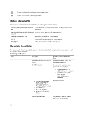
...connected to an electrical outlet, the battery light operates as follows: Alternately blinking amber light and white An unauthenticated or unsupported non-Dell AC adapter is attached to light your computer is unable to indicate battery charge status. Turns on steadily or blinks to complete a... of failure. White light on self test. Diagnostic Beep Codes The following table shows the possible beep codes that memory if the issue persists • issue with the memory connector 3 • Chipset Error (North and System board failure South Bridge Chipset, DMA/IMR/Timer Error) &#...
...connected to an electrical outlet, the battery light operates as follows: Alternately blinking amber light and white An unauthenticated or unsupported non-Dell AC adapter is attached to light your computer is unable to indicate battery charge status. Turns on steadily or blinks to complete a... of failure. White light on self test. Diagnostic Beep Codes The following table shows the possible beep codes that memory if the issue persists • issue with the memory connector 3 • Chipset Error (North and System board failure South Bridge Chipset, DMA/IMR/Timer Error) &#...
Owner's Manual
Page 47
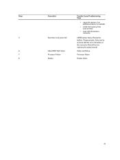
Beep 5 6 7 8 Description Real-time clock power fail Video BIOS Test Failure Processor Failure Display Possible Cause/Troubleshooting Steps • reseat the memory if an additional memory is available • install that will involve replacing the system board) Video card failure Processor failure Display failure 47 Reseat the battery. If issue persists, there can be an issue with the coin-cell battery or the connector (that memory if the issue persists • issue with the memory connector CMOS battery failure.
Beep 5 6 7 8 Description Real-time clock power fail Video BIOS Test Failure Processor Failure Display Possible Cause/Troubleshooting Steps • reseat the memory if an additional memory is available • install that will involve replacing the system board) Video card failure Processor failure Display failure 47 Reseat the battery. If issue persists, there can be an issue with the coin-cell battery or the connector (that memory if the issue persists • issue with the memory connector CMOS battery failure.
Owner's Manual
Page 49
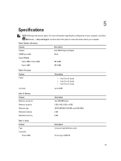
... Express Chipset DRAM bus width 64-bit Flash EPROM: Vostro 3360 / Vostro 3460 SPI 8 MB Vostro 3560 SPI 6 MB Table 9. Audio Feature Type Controller: Vostro 3360 Description 2 channel high definition audio Cirrus Logic CS4213D 49 5 Specifications NOTE: Offerings may vary by region. Memory Feature Memory connector Memory capacity Memory type Minimum memory Maximum memory Description two SODIMM slots 2 GB, 4 GB, 6 GB, or...
... Express Chipset DRAM bus width 64-bit Flash EPROM: Vostro 3360 / Vostro 3460 SPI 8 MB Vostro 3560 SPI 6 MB Table 9. Audio Feature Type Controller: Vostro 3360 Description 2 channel high definition audio Cirrus Logic CS4213D 49 5 Specifications NOTE: Offerings may vary by region. Memory Feature Memory connector Memory capacity Memory type Minimum memory Maximum memory Description two SODIMM slots 2 GB, 4 GB, 6 GB, or...


