Setup and Quick Reference Guide
Page 33
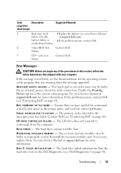
...Dell (see "Contacting Dell" on page 64). The primary cache internal to commands from the computer. The hard drive cannot read the data. One or more memory modules may be faulty or improperly seated. The hard drive failed initialization. Run the hard drive.... DATA ERROR - Reinstall the memory modules and, if necessary, replace them. C A C H E D I S A B L E D D U E T O F A I A R Y DEVICE FAILURE - See your Service Manual failure. Contact Dell (see "Dell Diagnostics" on page 38). motherboard failure. 6 Video BIOS Test Contact Dell. AU X I L I L U R E - If the...
...Dell (see "Contacting Dell" on page 64). The primary cache internal to commands from the computer. The hard drive cannot read the data. One or more memory modules may be faulty or improperly seated. The hard drive failed initialization. Run the hard drive.... DATA ERROR - Reinstall the memory modules and, if necessary, replace them. C A C H E D I S A B L E D D U E T O F A I A R Y DEVICE FAILURE - See your Service Manual failure. Contact Dell (see "Dell Diagnostics" on page 38). motherboard failure. 6 Video BIOS Test Contact Dell. AU X I L I L U R E - If the...

Setup and Quick Reference Guide
Page 34
...from a CD. Reinstall the memory modules and, if necessary, replace them. H A R D - Then, shut down the computer, reinstall the hard drive, and restart the computer. Run the Hard Disk Drive tests in filenames. The hard drive does not respond to fit on the disk, or the ... unable to a different disk or use these characters in the Dell Diagnostics (see "Dell Diagnostics" on page 64). Restart the computer. H A R D - The operation requires a hard drive in the Dell Diagnostics (see "Dell Diagnostics" on support.dell.com), and boot the computer from the computer. See your ...
...from a CD. Reinstall the memory modules and, if necessary, replace them. H A R D - Then, shut down the computer, reinstall the hard drive, and restart the computer. Run the Hard Disk Drive tests in filenames. The hard drive does not respond to fit on the disk, or the ... unable to a different disk or use these characters in the Dell Diagnostics (see "Dell Diagnostics" on page 64). Restart the computer. H A R D - The operation requires a hard drive in the Dell Diagnostics (see "Dell Diagnostics" on support.dell.com), and boot the computer from the computer. See your ...

Setup and Quick Reference Guide
Page 36
... boot device, ensure that you are attempting to use. 36 Troubleshooting If the hard drive is your Service Manual at support.dell.com for more information. Contact Dell (see the software documentation. NOT ENOUGH MEMORY OR RESOURCES. Reinstall the memory modules and, if necessary, replace them . M EMORY A L L O C A T I V E - If the error message still appears, see "Contacting...
... boot device, ensure that you are attempting to use. 36 Troubleshooting If the hard drive is your Service Manual at support.dell.com for more information. Contact Dell (see the software documentation. NOT ENOUGH MEMORY OR RESOURCES. Reinstall the memory modules and, if necessary, replace them . M EMORY A L L O C A T I V E - If the error message still appears, see "Contacting...
Service Manual
Page 19
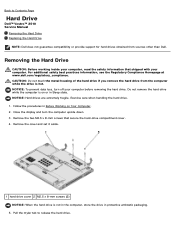
... Contents Page Hard Drive Dell™ Vostro™ 2510 Service Manual Removing the Hard Drive Replacing the Hard Drive NOTE: Dell does not guarantee compatibility or provide support for hard drives obtained from the computer while the drive is not in the computer, store the drive in Sleep state. Remove the cover and set it aside. 1 hard drive cover 2 M2.5 x 8-mm screws (2) NOTICE: When the hard drive is hot...
... Contents Page Hard Drive Dell™ Vostro™ 2510 Service Manual Removing the Hard Drive Replacing the Hard Drive NOTE: Dell does not guarantee compatibility or provide support for hard drives obtained from the computer while the drive is not in the computer, store the drive in Sleep state. Remove the cover and set it aside. 1 hard drive cover 2 M2.5 x 8-mm screws (2) NOTICE: When the hard drive is hot...

Service Manual
Page 20
... Removing the Hard Drive. 1. Lift the hard drive out of the computer. 1 hard drive Replacing the Hard Drive CAUTION: Before working inside your computer. Replace the two M2.5 x 8-mm screws to slide the hard drive into the hard drive connector until the drive is fully seated. 2. For information on reinstalling drivers and utilities, see the Regulatory Compliance Homepage at www.dell.com/regulatory_compliance. NOTICE: Hard drives are extremely...
... Removing the Hard Drive. 1. Lift the hard drive out of the computer. 1 hard drive Replacing the Hard Drive CAUTION: Before working inside your computer. Replace the two M2.5 x 8-mm screws to slide the hard drive into the hard drive connector until the drive is fully seated. 2. For information on reinstalling drivers and utilities, see the Regulatory Compliance Homepage at www.dell.com/regulatory_compliance. NOTICE: Hard drives are extremely...
Service Manual
Page 21
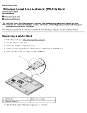
Remove the hard drive compartment cover. 4. Slide the WLAN card at www.dell.com/regulatory_compliance. Back to Contents Page Wireless Local Area Network (WLAN) Card Dell™ Vostro™ 2510 Service Manual Removing a WLAN Card Replacing a WLAN Card CAUTION: Before working inside your computer, read the safety information that shipped with your computer. Removing a WLAN Card 1. Follow the...
Remove the hard drive compartment cover. 4. Slide the WLAN card at www.dell.com/regulatory_compliance. Back to Contents Page Wireless Local Area Network (WLAN) Card Dell™ Vostro™ 2510 Service Manual Removing a WLAN Card Replacing a WLAN Card CAUTION: Before working inside your computer, read the safety information that shipped with your computer. Removing a WLAN Card 1. Follow the...

Service Manual
Page 22
... connector labeled "main" (white triangle), and connect the black antenna cable to the WLAN card, never place cables under the card. Replace the hard drive compartment cover. Back to the gray triangle. 3. 7. Rotate each antenna cable until it is positioned away from the WLAN card and ... on the cable to disconnect it. 1 antenna cables (2) 3 system board connector 2 WLAN card Replacing a WLAN Card NOTICE: The connectors are installing. Replace the tape that secures the WLAN card. 4. Replace the M2 x 3-mm screw that secures the two antenna cables on the system board, and realign...
... connector labeled "main" (white triangle), and connect the black antenna cable to the WLAN card, never place cables under the card. Replace the hard drive compartment cover. Back to the gray triangle. 3. 7. Rotate each antenna cable until it is positioned away from the WLAN card and ... on the cable to disconnect it. 1 antenna cables (2) 3 system board connector 2 WLAN card Replacing a WLAN Card NOTICE: The connectors are installing. Replace the tape that secures the WLAN card. 4. Replace the M2 x 3-mm screw that secures the two antenna cables on the system board, and realign...
Service Manual
Page 41
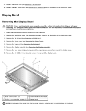
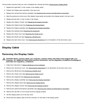
Replace the hard drive cover. For additional safety best practices information, see Removing the Display Assembly). 7. Follow the instructions in Before Working on Your Computer. 2. Remove the display assembly (see the Regulatory Compliance Homepage at www.dell.com/regulatory_compliance. 1. Display Bezel ... mylar screw-covers from the top cover requires extreme care to avoid damage to the bezel. Replace the WLAN card (see Removing a WLAN Card). 4. See Removing the Hard Drive for an illustration of the bezel from around the display bezel. 1 mylar screw covers (2) ...
Replace the hard drive cover. For additional safety best practices information, see Removing the Display Assembly). 7. Follow the instructions in Before Working on Your Computer. 2. Remove the display assembly (see the Regulatory Compliance Homepage at www.dell.com/regulatory_compliance. 1. Display Bezel ... mylar screw-covers from the top cover requires extreme care to avoid damage to the bezel. Replace the WLAN card (see Removing a WLAN Card). 4. See Removing the Hard Drive for an illustration of the bezel from around the display bezel. 1 mylar screw covers (2) ...
Service Manual
Page 42
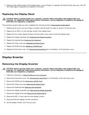
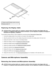
... shipped with your fingers to separate the bezel from the display inverter. 9. Replace the hinge cover (see Removing a WLAN Card). 4. For additional safety best practices information, see the Regulatory Compliance Homepage at www.dell.com/regulatory_compliance. See Removing the Hard Drive for an illustration of the display panel, use your computer, read the safety...
... shipped with your fingers to separate the bezel from the display inverter. 9. Replace the hinge cover (see Removing a WLAN Card). 4. For additional safety best practices information, see the Regulatory Compliance Homepage at www.dell.com/regulatory_compliance. See Removing the Hard Drive for an illustration of the display panel, use your computer, read the safety...
Service Manual
Page 43
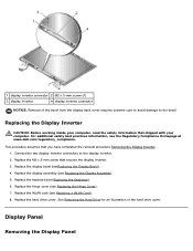
... keyboard (see Replacing the Display Assembly). 5. Replace the M2 x 3-mm screw that secures the display inverter. 3. Replace the hinge cover (see Replacing a WLAN Card). 8. Display Panel Removing the Display Panel Replace the WLAN card (see Replacing the Hinge Cover). 7. Replace the hard drive cover. For additional safety best practices information, see the Regulatory Compliance Homepage at www.dell.com/regulatory_compliance.
... keyboard (see Replacing the Display Assembly). 5. Replace the M2 x 3-mm screw that secures the display inverter. 3. Replace the hinge cover (see Replacing a WLAN Card). 8. Display Panel Removing the Display Panel Replace the WLAN card (see Replacing the Hinge Cover). 7. Replace the hard drive cover. For additional safety best practices information, see the Regulatory Compliance Homepage at www.dell.com/regulatory_compliance.
Service Manual
Page 44
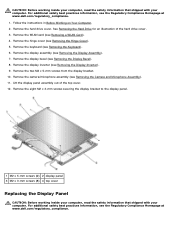
...Display Bezel). 8. Lift the display panel assembly out of the hard drive cover. 3. For additional safety best practices information, see the Regulatory Compliance Homepage at www.dell.com/regulatory_compliance. 1. See Removing the Hard Drive for an illustration of the top cover. 12. Remove the ...see the Regulatory Compliance Homepage at www.dell.com/regulatory_compliance. Remove the eight M2 x 3-mm screws securing the display bracket to the display panel. 1 M2 x 5-mm screws (2) 2 display panel 3 M2 x 3-mm screws (8) 4 top cover Replacing the Display Panel CAUTION: Before working ...
...Display Bezel). 8. Lift the display panel assembly out of the hard drive cover. 3. For additional safety best practices information, see the Regulatory Compliance Homepage at www.dell.com/regulatory_compliance. 1. See Removing the Hard Drive for an illustration of the top cover. 12. Remove the ...see the Regulatory Compliance Homepage at www.dell.com/regulatory_compliance. Remove the eight M2 x 3-mm screws securing the display bracket to the display panel. 1 M2 x 5-mm screws (2) 2 display panel 3 M2 x 3-mm screws (8) 4 top cover Replacing the Display Panel CAUTION: Before working ...
Service Manual
Page 45
...WLAN card (see Removing the Display Assembly). 7. Remove the display assembly (see Removing a WLAN Card). 4. Replace the two M2 x 5-mm screws in the display panel. 2. Replace the hard drive cover. Remove the two M2 x 5-mm screws from the connector on Your Computer. 2. Lift the display ...bracket. 11. Position the display panel assembly in the top cover. 5. Align the guide pins at www.dell.com/regulatory_compliance. 1. Replace the display bezel (see Replacing the Display Bezel). 8. Follow the instructions in Before Working on the back of the hard drive cover.
...WLAN card (see Removing the Display Assembly). 7. Remove the display assembly (see Removing a WLAN Card). 4. Replace the two M2 x 5-mm screws in the display panel. 2. Replace the hard drive cover. Remove the two M2 x 5-mm screws from the connector on Your Computer. 2. Lift the display ...bracket. 11. Position the display panel assembly in the top cover. 5. Align the guide pins at www.dell.com/regulatory_compliance. 1. Replace the display bezel (see Replacing the Display Bezel). 8. Follow the instructions in Before Working on the back of the hard drive cover.
Service Manual
Page 46
... Homepage at www.dell.com/regulatory_compliance. Replace the display inverter (see Replacing the Display Bezel). 6. Replace the display bezel (see Replacing the Display Inverter). 5. Replace the hinge cover (see Replacing the Display Assembly). 7. Replace the display assembly (see Replacing the Hinge Cover). 9. Replace the hard drive cover. Align the guide pins at the top of the hard drive cover. See Removing the Hard Drive for an...
... Homepage at www.dell.com/regulatory_compliance. Replace the display inverter (see Replacing the Display Bezel). 6. Replace the display bezel (see Replacing the Display Inverter). 5. Replace the hinge cover (see Replacing the Display Assembly). 7. Replace the display assembly (see Replacing the Hinge Cover). 9. Replace the hard drive cover. Align the guide pins at the top of the hard drive cover. See Removing the Hard Drive for an...
Service Manual
Page 47
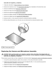
... Display Bezel). 4. Lift the camera/microphone out of the hard drive cover. 3. www.dell.com/regulatory_compliance. 1. Follow the instructions in the top cover and replace the M2 x 3- Remove the hard drive cover. Remove the display bezel (see the Regulatory Compliance Homepage at www.dell.com/regulatory_compliance. Remove the M2 x 3-mm screw that shipped with your computer, read...
... Display Bezel). 4. Lift the camera/microphone out of the hard drive cover. 3. www.dell.com/regulatory_compliance. 1. Follow the instructions in the top cover and replace the M2 x 3- Remove the hard drive cover. Remove the display bezel (see the Regulatory Compliance Homepage at www.dell.com/regulatory_compliance. Remove the M2 x 3-mm screw that shipped with your computer, read...

Service Manual
Page 48
Replace the hinge cover (see Replacing a WLAN Card). 8. Replace the WLAN card (see Replacing the Hinge Cover). 7. Replace the hard drive cover. See Removing the Hard Drive for an illustration of the hard drive cover. Replace the keyboard (see Replacing the Keyboard). 6. 5. Back to Contents Page
Replace the hinge cover (see Replacing a WLAN Card). 8. Replace the WLAN card (see Replacing the Hinge Cover). 7. Replace the hard drive cover. See Removing the Hard Drive for an illustration of the hard drive cover. Replace the keyboard (see Replacing the Keyboard). 6. 5. Back to Contents Page
Service Manual
Page 49
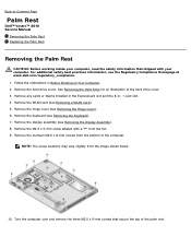
...the top of the hard drive cover. 3. Turn the computer over and remove the three M2.5 x 5-mm screws that shipped with a "P" from the image shown below. 10. Back to Contents Page Palm Rest Dell™ Vostro™ 2510 Service Manual Removing the Palm Rest Replacing the Palm Rest ...Removing the Palm Rest CAUTION: Before working inside your computer. See Removing the Hard Drive for an illustration of the palm rest. Remove the hinge cover...
...the top of the hard drive cover. 3. Turn the computer over and remove the three M2.5 x 5-mm screws that shipped with a "P" from the image shown below. 10. Back to Contents Page Palm Rest Dell™ Vostro™ 2510 Service Manual Removing the Palm Rest Replacing the Palm Rest ...Removing the Palm Rest CAUTION: Before working inside your computer. See Removing the Hard Drive for an illustration of the palm rest. Remove the hinge cover...
Service Manual
Page 51
... rest. 7. Replace the WLAN card (see the Regulatory Compliance Homepage at www.dell.com/regulatory_compliance. Connect the finger print reader connector to the system board. 4. Replace the hard drive cover. Replace the M2.5 x 5-mm screw in -1 card slot. Replace the display assembly (see Replacing the Display Assembly...8- Connect the touchpad connector to the system board. 6. Turn the computer upside down and replace the fourteen M2.5 x 8-mm screws on the fan. 9. See Removing the Hard Drive for the internal card with a "P" on the bottom of the palm rest. 3. Connect...
... rest. 7. Replace the WLAN card (see the Regulatory Compliance Homepage at www.dell.com/regulatory_compliance. Connect the finger print reader connector to the system board. 4. Replace the hard drive cover. Replace the M2.5 x 5-mm screw in -1 card slot. Replace the display assembly (see Replacing the Display Assembly...8- Connect the touchpad connector to the system board. 6. Turn the computer upside down and replace the fourteen M2.5 x 8-mm screws on the fan. 9. See Removing the Hard Drive for the internal card with a "P" on the bottom of the palm rest. 3. Connect...
Service Manual
Page 52
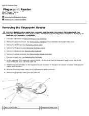
... x 3-mm screw 2 fingerprint reader cover reader cable connector. 10. Back to release the fingerprint- See Removing the Hard Drive for an illustration of the hard drive cover. 3. Remove the keyboard (see Removing the Hinge Cover). 5. Remove the hinge cover (see Removing the Keyboard).... Follow the instructions in Before Working on the palm rest upward to Contents Page Fingerprint Reader Dell™ Vostro™ 2510 Service Manual Removing the Fingerprint Reader Replacing the Fingerprint Reader Removing the Fingerprint Reader CAUTION: Before working inside your computer, read the...
... x 3-mm screw 2 fingerprint reader cover reader cable connector. 10. Back to release the fingerprint- See Removing the Hard Drive for an illustration of the hard drive cover. 3. Remove the keyboard (see Removing the Hinge Cover). 5. Remove the hinge cover (see Removing the Keyboard).... Follow the instructions in Before Working on the palm rest upward to Contents Page Fingerprint Reader Dell™ Vostro™ 2510 Service Manual Removing the Fingerprint Reader Replacing the Fingerprint Reader Removing the Fingerprint Reader CAUTION: Before working inside your computer, read the...
Service Manual
Page 53
... inside your computer. For additional safety best practices information, see Replacing the Palm Rest). 5. Replace the palm rest (see the Regulatory Compliance Homepage at www.dell.com/regulatory_compliance. Replace the hard drive cover. NOTICE: Ensure that secures the cover to Contents Page See Removing the Hard Drive for the internal card with your computer, read the safety information...
... inside your computer. For additional safety best practices information, see Replacing the Palm Rest). 5. Replace the palm rest (see the Regulatory Compliance Homepage at www.dell.com/regulatory_compliance. Replace the hard drive cover. NOTICE: Ensure that secures the cover to Contents Page See Removing the Hard Drive for the internal card with your computer, read the safety information...
Service Manual
Page 54
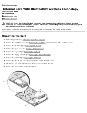
... Contents Page Internal Card With Bluetooth® Wireless Technology Dell™ Vostro™ 2510 Service Manual Removing the Card Replacing the Card CAUTION: Before working inside your computer, read the safety information that connects the card to the USB board. 9. Removing the Card 1. Remove the hard drive cover. Remove the palm rest (see the Regulatory Compliance...
... Contents Page Internal Card With Bluetooth® Wireless Technology Dell™ Vostro™ 2510 Service Manual Removing the Card Replacing the Card CAUTION: Before working inside your computer, read the safety information that connects the card to the USB board. 9. Removing the Card 1. Remove the hard drive cover. Remove the palm rest (see the Regulatory Compliance...


