Setup and Features Information Tech Sheet
Page 2
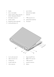
1 display 2 3 device status lights 4 5 media controls (volume, forward, 6 reverse, stop, play, and eject) 7 AC adapter connector 8 9 wireless switch 10 11 fingerprint reader (optional) 12 13 touch pad buttons (2) power button keyboard status lights keyboard USB connectors (2) optical drive/media bay touch pad 10 1 8-in-1 card reader slot 3 audio connectors (2) 5 cooling vents 7 security cable slot 9 video connector 9 87 5 6 2 ExpressCard/54 slot 4 IEEE 1394 connector 6 USB connector 8 network connector 10 battery 3 21 4
1 display 2 3 device status lights 4 5 media controls (volume, forward, 6 reverse, stop, play, and eject) 7 AC adapter connector 8 9 wireless switch 10 11 fingerprint reader (optional) 12 13 touch pad buttons (2) power button keyboard status lights keyboard USB connectors (2) optical drive/media bay touch pad 10 1 8-in-1 card reader slot 3 audio connectors (2) 5 cooling vents 7 security cable slot 9 video connector 9 87 5 6 2 ExpressCard/54 slot 4 IEEE 1394 connector 6 USB connector 8 network connector 10 battery 3 21 4
Setup and Features Information Tech Sheet
Page 4
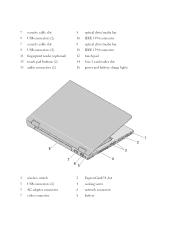
7 security cable slot 9 USB connectors (2) 7 security cable slot 9 USB connectors (2) 11 fingerprint reader (optional) 13 touch pad buttons (2) 15 audio connectors (2) 8 optical drive/media bay 10 IEEE 1394 connector 8 optical drive/media bay 10 IEEE 1394 connector 12 touch pad 14 8-in-1 card reader slot 16 power and battery charge lights 8 7 4 65 1 wireless switch 3 USB connectors (2) 5 AC adapter connector 7 video connector 2 ExpressCard/54 slot 4 cooling vents 6 network connector 8 battery 1 2 3
7 security cable slot 9 USB connectors (2) 7 security cable slot 9 USB connectors (2) 11 fingerprint reader (optional) 13 touch pad buttons (2) 15 audio connectors (2) 8 optical drive/media bay 10 IEEE 1394 connector 8 optical drive/media bay 10 IEEE 1394 connector 12 touch pad 14 8-in-1 card reader slot 16 power and battery charge lights 8 7 4 65 1 wireless switch 3 USB connectors (2) 5 AC adapter connector 7 video connector 2 ExpressCard/54 slot 4 cooling vents 6 network connector 8 battery 1 2 3
Setup and Features Information Tech Sheet
Page 5
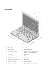
Vostro 1710 1 2 3 4 5 6 9 7 A 18 17 16 15 14 8 9 10 13 11 12 1 display latches 3 power button 5 keyboard status lights 7 keyboard 9 optical drive/media bay 11 IEEE 1394 connector 13 fingerprint reader (optional) 15 touch pad buttons(2) 17 audio connectors(2) 2 display 4 device status lights 6 media controls (volume, forward, reverse, stop, play, and eject) 8 security lock 10 USB connectors (2) 12 wireless switch 14 touch pad 16 8-in-1 card reader 18 power and battery charge lights
Vostro 1710 1 2 3 4 5 6 9 7 A 18 17 16 15 14 8 9 10 13 11 12 1 display latches 3 power button 5 keyboard status lights 7 keyboard 9 optical drive/media bay 11 IEEE 1394 connector 13 fingerprint reader (optional) 15 touch pad buttons(2) 17 audio connectors(2) 2 display 4 device status lights 6 media controls (volume, forward, reverse, stop, play, and eject) 8 security lock 10 USB connectors (2) 12 wireless switch 14 touch pad 16 8-in-1 card reader 18 power and battery charge lights
Setup and Quick Reference Guide
Page 3
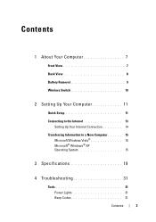
Contents 1 About Your Computer 7 Front View 7 Back View 8 Battery Removal 9 Wireless Switch 10 2 Setting Up Your Computer 11 Quick Setup 11 Connecting to the Internet 13 Setting Up Your Internet Connection 14 Transferring Information to a New Computer 15 Microsoft Windows Vista 15 Microsoft® Windows® XP Operating System 15 3 Specifications 19 4 Troubleshooting 31 Tools 31 Power Lights 31 Beep Codes 31 Contents 3
Contents 1 About Your Computer 7 Front View 7 Back View 8 Battery Removal 9 Wireless Switch 10 2 Setting Up Your Computer 11 Quick Setup 11 Connecting to the Internet 13 Setting Up Your Internet Connection 14 Transferring Information to a New Computer 15 Microsoft Windows Vista 15 Microsoft® Windows® XP Operating System 15 3 Specifications 19 4 Troubleshooting 31 Tools 31 Power Lights 31 Beep Codes 31 Contents 3
Setup and Quick Reference Guide
Page 9
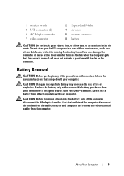
... the fan when the computer gets hot. Fan noise is running. Battery Removal CAUTION: Before you begin any other computers with your Dell™ computer. Replace the battery only with the fan or the computer. Restricting the airflow can damage the computer or cause a ... electrical outlet and the computer, disconnect the modem from the wall connector and computer, and remove any of fire or explosion. About Your Computer 9 1 wireless switch 3 USB connectors (2) 5 AC Adapter connector 7 video connector 2 ExpressCard/54 slot 4 air vents 6 network connector 8 battery CAUTION: Do not ...
... the fan when the computer gets hot. Fan noise is running. Battery Removal CAUTION: Before you begin any other computers with your Dell™ computer. Replace the battery only with the fan or the computer. Restricting the airflow can damage the computer or cause a ... electrical outlet and the computer, disconnect the modem from the wall connector and computer, and remove any of fire or explosion. About Your Computer 9 1 wireless switch 3 USB connectors (2) 5 AC Adapter connector 7 video connector 2 ExpressCard/54 slot 4 air vents 6 network connector 8 battery CAUTION: Do not ...
Setup and Quick Reference Guide
Page 10
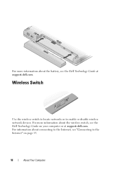
Wireless Switch Use the wireless switch to locate networks or to the Internet" on your computer or at support.dell.com. For more information about the battery, see the Dell Technology Guide at support.dell.com. For more information about the wireless switch, see the Dell Technology Guide on page 13. 10 About Your Computer For information about connecting to the Internet, see "Connecting to enable or disable wireless network devices.
Wireless Switch Use the wireless switch to locate networks or to the Internet" on your computer or at support.dell.com. For more information about the battery, see the Dell Technology Guide at support.dell.com. For more information about the wireless switch, see the Dell Technology Guide on page 13. 10 About Your Computer For information about connecting to the Internet, see "Connecting to enable or disable wireless network devices.

Setup and Quick Reference Guide
Page 13
... connection. If you are using a DSL or cable/satellite modem connection, contact your ISP or cellular phone service for more information. 4 5 3 2 1 3 2 1 1 Internet service 3 wireless router 5 laptop computer with wireless network card 2 cable or DSL modem 4 laptop computer with network adapter Connecting to the telephone wall connector before you set up your computer...
... connection. If you are using a DSL or cable/satellite modem connection, contact your ISP or cellular phone service for more information. 4 5 3 2 1 3 2 1 1 Internet service 3 wireless router 5 laptop computer with wireless network card 2 cable or DSL modem 4 laptop computer with network adapter Connecting to the telephone wall connector before you set up your computer...
Setup and Quick Reference Guide
Page 15
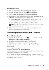
...) or Dial-up, depending on how you want to connect: • Choose Broadband if you will use a DSL, satellite modem, cable TV modem, or Bluetooth wireless technology connection. • Chose Dial-up modem or ISDN. Follow the instructions provided on removable media, such as a writable CD, for transfer to complete the...
...) or Dial-up, depending on how you want to connect: • Choose Broadband if you will use a DSL, satellite modem, cable TV modem, or Bluetooth wireless technology connection. • Chose Dial-up modem or ISDN. Follow the instructions provided on removable media, such as a writable CD, for transfer to complete the...
Setup and Quick Reference Guide
Page 21
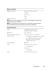
...microphone connector, stereo headphone/speakers connector 4-pin connector Vostro 1310, 1510, 1710, and 2510: • one USB-based daughter card with Bluetooth® wireless technology (Dell™ Wireless 360) RJ-45 port Vostro 1310, 1510, and 2510: • four USB ports Vostro 1710: • six USB ports 15-pin ...memory is reserved for WLAN • one dedicated Mini-Card slot for system files. Memory (continued) Minimum memory Vostro 1310, 1510, and 1710: 512 MB Vostro 2510: 1 GB Maximum memory 4 GB NOTE: In order to take advantage of the dual-channel bandwidth capability, both...
...microphone connector, stereo headphone/speakers connector 4-pin connector Vostro 1310, 1510, 1710, and 2510: • one USB-based daughter card with Bluetooth® wireless technology (Dell™ Wireless 360) RJ-45 port Vostro 1310, 1510, and 2510: • four USB ports Vostro 1710: • six USB ports 15-pin ...memory is reserved for WLAN • one dedicated Mini-Card slot for system files. Memory (continued) Minimum memory Vostro 1310, 1510, and 1710: 512 MB Vostro 2510: 1 GB Maximum memory 4 GB NOTE: In order to take advantage of the dual-channel bandwidth capability, both...
Setup and Quick Reference Guide
Page 22
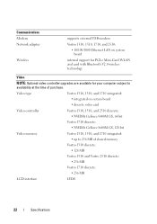
... 256 MB of purchase. Communications Modem Network adapter Wireless supports external USB modem Vostro 1310, 1510, 1710, and 2510: • 10/100/1000 Ethernet LAN on system board • discrete video card Video controller Vostro 1310, 1510, and 2510 discrete: • NVIDIA GeForce 8400M GS, 64 bit Vostro 1710 discrete: • NVIDIA GeForce 8600M GS, 128...
... 256 MB of purchase. Communications Modem Network adapter Wireless supports external USB modem Vostro 1310, 1510, 1710, and 2510: • 10/100/1000 Ethernet LAN on system board • discrete video card Video controller Vostro 1310, 1510, and 2510 discrete: • NVIDIA GeForce 8400M GS, 64 bit Vostro 1710 discrete: • NVIDIA GeForce 8600M GS, 128...
Setup and Quick Reference Guide
Page 58
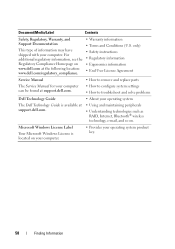
For additional regulatory information, see the Regulatory Compliance Homepage on www.dell.com at support.dell.com. • Using and maintaining peripherals • Understanding technologies such as RAID, Internet, Bluetooth® wireless technology, e-mail, and so on your computer. • Provides your computer. only) • Safety instructions • Regulatory information • Ergonomics information •...
For additional regulatory information, see the Regulatory Compliance Homepage on www.dell.com at support.dell.com. • Using and maintaining peripherals • Understanding technologies such as RAID, Internet, Bluetooth® wireless technology, e-mail, and so on your computer. • Provides your computer. only) • Safety instructions • Regulatory information • Ergonomics information •...
Service Manual
Page 1
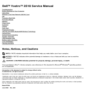
... Vista, and the Windows start button logo are not applicable. disclaims any manner whatsoever without notice. © 2008 Dell Inc. Dell™ Vostro™ 2510 Service Manual Troubleshooting Before Working on Your Computer Hard Drive Wireless Local Area Network (WLAN) Card Fan Processor Heat Sink Processor Module Memory Hinge Cover Keyboard Display Palm Rest Fingerprint...
... Vista, and the Windows start button logo are not applicable. disclaims any manner whatsoever without notice. © 2008 Dell Inc. Dell™ Vostro™ 2510 Service Manual Troubleshooting Before Working on Your Computer Hard Drive Wireless Local Area Network (WLAN) Card Fan Processor Heat Sink Processor Module Memory Hinge Cover Keyboard Display Palm Rest Fingerprint...
Service Manual
Page 21
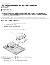
... card is already installed. Remove the hard drive compartment cover. 4. Slide the WLAN card at www.dell.com/regulatory_compliance. Turn the computer upside down. 3. Back to Contents Page Wireless Local Area Network (WLAN) Card Dell™ Vostro™ 2510 Service Manual Removing a WLAN Card Replacing a WLAN Card CAUTION: Before working inside your computer, read the...
... card is already installed. Remove the hard drive compartment cover. 4. Slide the WLAN card at www.dell.com/regulatory_compliance. Turn the computer upside down. 3. Back to Contents Page Wireless Local Area Network (WLAN) Card Dell™ Vostro™ 2510 Service Manual Removing a WLAN Card Replacing a WLAN Card CAUTION: Before working inside your computer, read the...
Service Manual
Page 51
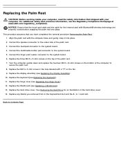
... palm rest. 7. Connect the touchpad connector to the system board. 5. Replace the WLAN card (see the Regulatory Compliance Homepage at www.dell.com/regulatory_compliance. See Removing the Hard Drive for the internal card with a "P" on the fan. 9. For additional safety best practices information... secure the palm rest. 8. Replace the hinge cover (see Replacing the Keyboard). 11. in the hole labeled with Bluetooth® wireless technology are properly routed before snapping the palm rest into place. 2. Replace the keyboard (see Replacing the Hinge Cover). 12. Replace...
... palm rest. 7. Connect the touchpad connector to the system board. 5. Replace the WLAN card (see the Regulatory Compliance Homepage at www.dell.com/regulatory_compliance. See Removing the Hard Drive for the internal card with a "P" on the fan. 9. For additional safety best practices information... secure the palm rest. 8. Replace the hinge cover (see Replacing the Keyboard). 11. in the hole labeled with Bluetooth® wireless technology are properly routed before snapping the palm rest into place. 2. Replace the keyboard (see Replacing the Hinge Cover). 12. Replace...
Service Manual
Page 53
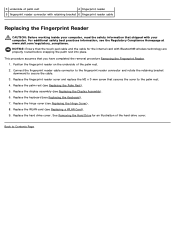
... Position the fingerprint reader on the underside of the hard drive cover. Replace the palm rest (see the Regulatory Compliance Homepage at www.dell.com/regulatory_compliance. Replace the hard drive cover. 3 underside of palm rest 4 fingerprint reader 5 fingerprint reader connector with retaining bracket 6 ...See Removing the Hard Drive for the internal card with your computer, read the safety information that shipped with Bluetooth® wireless technology are properly routed before snapping the palm rest into place. NOTICE: Ensure that the touch pad cable and the cable ...
... Position the fingerprint reader on the underside of the hard drive cover. Replace the palm rest (see the Regulatory Compliance Homepage at www.dell.com/regulatory_compliance. Replace the hard drive cover. 3 underside of palm rest 4 fingerprint reader 5 fingerprint reader connector with retaining bracket 6 ...See Removing the Hard Drive for the internal card with your computer, read the safety information that shipped with Bluetooth® wireless technology are properly routed before snapping the palm rest into place. NOTICE: Ensure that the touch pad cable and the cable ...
Service Manual
Page 54
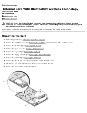
... Remove the palm rest (see Removing the Display Assembly). 7. Back to Contents Page Internal Card With Bluetooth® Wireless Technology Dell™ Vostro™ 2510 Service Manual Removing the Card Replacing the Card CAUTION: Before working inside your computer, read the safety information that connects ...compartment. See Removing the Hard Drive for an illustration of the hard drive cover. 3. If you ordered a card with Bluetooth wireless technology with your computer, the card is already installed. Follow the procedures in Before Working on Your Computer. 2. Removing the ...
... Remove the palm rest (see Removing the Display Assembly). 7. Back to Contents Page Internal Card With Bluetooth® Wireless Technology Dell™ Vostro™ 2510 Service Manual Removing the Card Replacing the Card CAUTION: Before working inside your computer, read the safety information that connects ...compartment. See Removing the Hard Drive for an illustration of the hard drive cover. 3. If you ordered a card with Bluetooth wireless technology with your computer, the card is already installed. Follow the procedures in Before Working on Your Computer. 2. Removing the ...
Service Manual
Page 64
... the computer base. Remove the WLAN card (see Removing the Card). 9. Back to Contents Page USB Daughter Card Dell™ Vostro™ 2510 Service Manual Removing the USB Daughter Card Replacing the USB Daughter Card Removing the USB Daughter Card CAUTION: Before working ...inside your computer, read the safety information that shipped with Bluetooth wireless technology, if installed (see Removing a WLAN Card). 4. Remove the hard drive cover. For additional safety best practices information, see the Regulatory Compliance Homepage at www.dell.com/regulatory_compliance. 1.
... the computer base. Remove the WLAN card (see Removing the Card). 9. Back to Contents Page USB Daughter Card Dell™ Vostro™ 2510 Service Manual Removing the USB Daughter Card Replacing the USB Daughter Card Removing the USB Daughter Card CAUTION: Before working ...inside your computer, read the safety information that shipped with Bluetooth wireless technology, if installed (see Removing a WLAN Card). 4. Remove the hard drive cover. For additional safety best practices information, see the Regulatory Compliance Homepage at www.dell.com/regulatory_compliance. 1.
Service Manual
Page 65
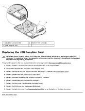
... connector 3 USB daughter card 2 M2.5 x 5-mm screw (1) Replacing the USB Daughter Card CAUTION: Before working inside your computer. This procedure assumes that shipped with Bluetooth wireless technology, if installed (see Removing the Card). 4. Replace the display assembly (see the Regulatory Compliance Homepage at www...
... connector 3 USB daughter card 2 M2.5 x 5-mm screw (1) Replacing the USB Daughter Card CAUTION: Before working inside your computer. This procedure assumes that shipped with Bluetooth wireless technology, if installed (see Removing the Card). 4. Replace the display assembly (see the Regulatory Compliance Homepage at www...
Service Manual
Page 66
...observe the orientation of the computer and unhook the battery latch assembly spring. Back to Contents Page Battery Latch Assembly Dell™ Vostro™ 2510 Service Manual Removing the Battery Latch Assembly Replacing the Battery Latch Assembly Removing the Battery Latch Assembly CAUTION: Before ...12. Remove the system board (see Removing the Palm Rest). 9. Remove the WLAN card (see the Regulatory Compliance Homepage at www.dell.com/regulatory_compliance. 1. For additional safety best practices information, see Removing a WLAN Card). 4. Push the alignment bracket to the left to...
...observe the orientation of the computer and unhook the battery latch assembly spring. Back to Contents Page Battery Latch Assembly Dell™ Vostro™ 2510 Service Manual Removing the Battery Latch Assembly Replacing the Battery Latch Assembly Removing the Battery Latch Assembly CAUTION: Before ...12. Remove the system board (see Removing the Palm Rest). 9. Remove the WLAN card (see the Regulatory Compliance Homepage at www.dell.com/regulatory_compliance. 1. For additional safety best practices information, see Removing a WLAN Card). 4. Push the alignment bracket to the left to...
Service Manual
Page 67
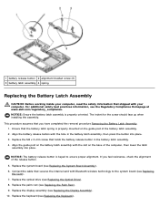
... Palm Rest). 9. If you have completed the removal procedure Removing the Battery Latch Assembly. 1. Replace the palm rest (see the Regulatory Compliance Homepage at www.dell.com/regulatory_compliance. Replace the optical drive (see Replacing the Optical Drive). 8. Replace the M2 x 3-mm screw that holds the battery release button in the battery... bracket screw (1) 3 battery latch assembly 4 spring Replacing the Battery Latch Assembly CAUTION: Before working inside your computer, read the safety information that shipped with Bluetooth wireless technology to ensure proper alignment.
... Palm Rest). 9. If you have completed the removal procedure Removing the Battery Latch Assembly. 1. Replace the palm rest (see the Regulatory Compliance Homepage at www.dell.com/regulatory_compliance. Replace the optical drive (see Replacing the Optical Drive). 8. Replace the M2 x 3-mm screw that holds the battery release button in the battery... bracket screw (1) 3 battery latch assembly 4 spring Replacing the Battery Latch Assembly CAUTION: Before working inside your computer, read the safety information that shipped with Bluetooth wireless technology to ensure proper alignment.


