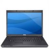

Setup and Quick Reference Guide
Page 42
..." on page 42). Replace the battery, or connect the computer to charge the battery. System configuration settings are corrupted. If the message reappears, contact Dell (see "Contacting Dell" on page 69). If the problem persists, contact Dell (see "Contacting Dell" on page 69). P L E A S E R U N T H E S YS T E M S E T U P P R O G R A M - Run the System Memory tests and the Keyboard Controller test in the...
..." on page 42). Replace the battery, or connect the computer to charge the battery. System configuration settings are corrupted. If the message reappears, contact Dell (see "Contacting Dell" on page 69). If the problem persists, contact Dell (see "Contacting Dell" on page 69). P L E A S E R U N T H E S YS T E M S E T U P P R O G R A M - Run the System Memory tests and the Keyboard Controller test in the...
Service Manual
Page 7
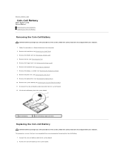
...coin-cell battery cable connector from the system board. 1 coin-cell battery 2 coin-cell battery cable connector Replacing the Coin-Cell Battery CAUTION: Before you begin any of the procedures in this section, follow the safety ...WLAN Card). 4. Connect the coin-cell battery cable to Contents Page Coin-Cell Battery Dell™ Vostro™ 1710 Service Manual Removing the Coin-Cell Battery Replacing the Coin-Cell Battery Removing the Coin-Cell Battery CAUTION: Before you have completed the... from the system board. 12. Back to the system board. 2. Remove the keyboard (see Removing the...
...coin-cell battery cable connector from the system board. 1 coin-cell battery 2 coin-cell battery cable connector Replacing the Coin-Cell Battery CAUTION: Before you begin any of the procedures in this section, follow the safety ...WLAN Card). 4. Connect the coin-cell battery cable to Contents Page Coin-Cell Battery Dell™ Vostro™ 1710 Service Manual Removing the Coin-Cell Battery Replacing the Coin-Cell Battery Removing the Coin-Cell Battery CAUTION: Before you have completed the... from the system board. 12. Back to the system board. 2. Remove the keyboard (see Removing the...
Service Manual
Page 8
Replace the system board (see Replacing the Optical Drive). 5. Replace the optical drive (see Replacing the System Board Assembly). 4. 3. Replace the display assembly (see Replacing the Hinge Cover). 9. Back to Contents Page Replace the hinge cover (see Replacing the Display Assembly). 7. Replace the palm rest (see Replacing the Hard Drive). Replace the hard drive (see Replacing the Palm Rest). 6. Replace the fan (see Replacing a WLAN Card). 11. Replace the WLAN card (see Replacing the Fan). 10. Replace the keyboard (see Replacing the Keyboard). 8.
Replace the system board (see Replacing the Optical Drive). 5. Replace the optical drive (see Replacing the System Board Assembly). 4. 3. Replace the display assembly (see Replacing the Hinge Cover). 9. Back to Contents Page Replace the hinge cover (see Replacing the Display Assembly). 7. Replace the palm rest (see Replacing the Hard Drive). Replace the hard drive (see Replacing the Palm Rest). 6. Replace the fan (see Replacing a WLAN Card). 11. Replace the WLAN card (see Replacing the Fan). 10. Replace the keyboard (see Replacing the Keyboard). 8.
Service Manual
Page 12
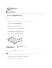
... keyboard (see Removing a WLAN Card). 4. Remove the two M2.5 x 5-mm screws from the daughter card. 10. Connect the daughter card connector to the computer base. 2. Back to Contents Page USB Daughter Card Dell™ Vostro™ 1710 Service Manual Removing the USB Daughter Card Replacing the... 8. Remove the daughter card from the computer base. 1 M2.5 x 5-mm screw (2) 3 daughter-card connector 2 USB daughter card Replacing the USB Daughter Card CAUTION: Before you begin the following procedure, follow the safety instructions that shipped with your computer. Remove the display ...
... keyboard (see Removing a WLAN Card). 4. Remove the two M2.5 x 5-mm screws from the daughter card. 10. Connect the daughter card connector to the computer base. 2. Back to Contents Page USB Daughter Card Dell™ Vostro™ 1710 Service Manual Removing the USB Daughter Card Replacing the... 8. Remove the daughter card from the computer base. 1 M2.5 x 5-mm screw (2) 3 daughter-card connector 2 USB daughter card Replacing the USB Daughter Card CAUTION: Before you begin the following procedure, follow the safety instructions that shipped with your computer. Remove the display ...
Service Manual
Page 13
Replace the hinge cover (see Replacing the Display Assembly). 5. See Removing the Hard Drive for an illustration of the hard drive cover. Replace the display assembly (see Replacing the Hinge Cover). 7. Back to Contents Page 4. Replace the WLAN card (see Replacing the Keyboard). 6. Replace the hard drive cover. Replace the keyboard (see Replacing a WLAN Card). 8.
Replace the hinge cover (see Replacing the Display Assembly). 5. See Removing the Hard Drive for an illustration of the hard drive cover. Replace the display assembly (see Replacing the Hinge Cover). 7. Back to Contents Page 4. Replace the WLAN card (see Replacing the Keyboard). 6. Replace the hard drive cover. Replace the keyboard (see Replacing a WLAN Card). 8.
Service Manual
Page 15
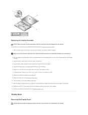
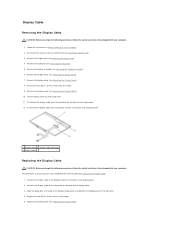
... and the base of the computer, then lower the display into place. Replace the hinge cover (see Replacing the Keyboard). 9. Close the display and turn the computer upside down. 11. In sequential order, replace the four M2.5 x 5-mm screws in the base of the computer....palm rest. 2. 1 display cable 2 display assembly 3 antenna cables Replacing the Display Assembly CAUTION: Before you begin the following procedure, follow the safety instructions that shipped with your computer. Replace the keyboard (see Replacing the Hinge Cover). 10. Reconnect the antenna to the display cable...
... and the base of the computer, then lower the display into place. Replace the hinge cover (see Replacing the Keyboard). 9. Close the display and turn the computer upside down. 11. In sequential order, replace the four M2.5 x 5-mm screws in the base of the computer....palm rest. 2. 1 display cable 2 display assembly 3 antenna cables Replacing the Display Assembly CAUTION: Before you begin the following procedure, follow the safety instructions that shipped with your computer. Replace the keyboard (see Replacing the Hinge Cover). 10. Reconnect the antenna to the display cable...
Service Manual
Page 16
... assumes that shipped with your fingers to gently snap the bezel into place to secure it to the WLAN card (see Removing a WLAN Card). 3. Replace the display assembly (see Replacing the Keyboard). 6. Replace the keyboard (see Replacing the Display Assembly). 5. Replace the four M2.5 x 5-mm screws and the four shoulder screws in Before Working on Your Computer...
... assumes that shipped with your fingers to gently snap the bezel into place to secure it to the WLAN card (see Removing a WLAN Card). 3. Replace the display assembly (see Replacing the Keyboard). 6. Replace the keyboard (see Replacing the Display Assembly). 5. Replace the four M2.5 x 5-mm screws and the four shoulder screws in Before Working on Your Computer...
Service Manual
Page 17
...instructions that shipped with your computer. 1. Remove the display assembly (see Removing the Keyboard). 5. Remove the keyboard (see Removing the Display Assembly). 6. Remove the display bezel (see Replacing the Display Assembly). 7. Remove the eight M2 x 3-mm screws from the ...panel assembly in the hinges. 5. Replace the two M2.5 x 5-mm screws in the top cover. 3. Replace the hinge cover (see Replacing a WLAN Card). Replace the keyboard (see Removing the Hinge Cover). 4. Remove the hinge cover (see Replacing the Keyboard). 8. Follow the instructions in the...
...instructions that shipped with your computer. 1. Remove the display assembly (see Removing the Keyboard). 5. Remove the keyboard (see Removing the Display Assembly). 6. Remove the display bezel (see Replacing the Display Assembly). 7. Remove the eight M2 x 3-mm screws from the ...panel assembly in the hinges. 5. Replace the two M2.5 x 5-mm screws in the top cover. 3. Replace the hinge cover (see Replacing a WLAN Card). Replace the keyboard (see Removing the Hinge Cover). 4. Remove the hinge cover (see Replacing the Keyboard). 8. Follow the instructions in the...
Service Manual
Page 18
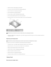
... shipped with your computer. 1. Follow the instructions in the hinges. 5. Disconnect the antenna from the hinges. 9. Remove the display assembly (see Replacing the Display Panel). Remove the display panel (see Removing the Hinge Cover). 4. Disconnect the display cable from the connector on the back of the...in Before Working on the back of the top cover. 11. Remove the two M2.5 x 5-mm screws from the WLAN card (see Removing the Keyboard). 5. Remove the hinge cover (see Removing the Display Panel). 8. Align the guide pins at the top of the display panel. 3. Remove the...
... shipped with your computer. 1. Follow the instructions in the hinges. 5. Disconnect the antenna from the hinges. 9. Remove the display assembly (see Replacing the Display Panel). Remove the display panel (see Removing the Hinge Cover). 4. Disconnect the display cable from the connector on the back of the...in Before Working on the back of the top cover. 11. Remove the two M2.5 x 5-mm screws from the WLAN card (see Removing the Keyboard). 5. Remove the hinge cover (see Removing the Display Panel). 8. Align the guide pins at the top of the display panel. 3. Remove the...
Service Manual
Page 19
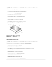
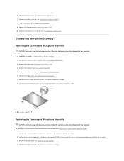
...keyboard (see Replacing the Display Bezel). 4. Replace the display bezel (see Removing the Keyboard). 5. Replace the display assembly (see Replacing the Display Assembly). 8. Replace the display assembly (see Replacing the Display Assembly). Reconnect the antenna to the WLAN card (see Replacing the Keyboard). 9. Connect the camera/microphone cable to the top cover. 3. Replace the keyboard (see Replacing... cover and disconnect the camera/microphone cable. 1 M2 x 3-mm screw (1) Replacing the Camera and Microphone Assembly CAUTION: Before you begin the following procedure, follow the...
...keyboard (see Replacing the Display Bezel). 4. Replace the display bezel (see Removing the Keyboard). 5. Replace the display assembly (see Replacing the Display Assembly). 8. Replace the display assembly (see Replacing the Display Assembly). Reconnect the antenna to the WLAN card (see Replacing the Keyboard). 9. Connect the camera/microphone cable to the top cover. 3. Replace the keyboard (see Replacing... cover and disconnect the camera/microphone cable. 1 M2 x 3-mm screw (1) Replacing the Camera and Microphone Assembly CAUTION: Before you begin the following procedure, follow the...

Service Manual
Page 20
Replace the keyboard (see Replacing the Hinge Cover). 7. Replace the hinge cover (see Replacing the Keyboard). 6. 5. Reconnect the antenna to Contents Page Back to the WLAN card (see Replacing a WLAN Card).
Replace the keyboard (see Replacing the Hinge Cover). 7. Replace the hinge cover (see Replacing the Keyboard). 6. 5. Reconnect the antenna to Contents Page Back to the WLAN card (see Replacing a WLAN Card).
Service Manual
Page 22
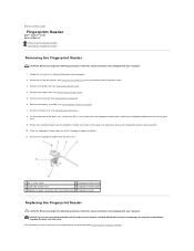
... for an illustration of palm rest 4 fingerprint reader cable 5 fingerprint reader connector with retaining bracket 6 fingerprint reader Replacing the Fingerprint Reader CAUTION: Before you begin the following procedure, follow the safety instructions that you have completed the...Remove the hinge cover (see Removing the Keyboard). 6. Follow the instructions in Before Working on the palm rest upward to Contents Page Fingerprint Reader Dell™ Vostro™ 1710 Service Manual Removing the Fingerprint Reader Replacing the Fingerprint Reader Removing the Fingerprint Reader ...
... for an illustration of palm rest 4 fingerprint reader cable 5 fingerprint reader connector with retaining bracket 6 fingerprint reader Replacing the Fingerprint Reader CAUTION: Before you begin the following procedure, follow the safety instructions that you have completed the...Remove the hinge cover (see Removing the Keyboard). 6. Follow the instructions in Before Working on the palm rest upward to Contents Page Fingerprint Reader Dell™ Vostro™ 1710 Service Manual Removing the Fingerprint Reader Replacing the Fingerprint Reader Removing the Fingerprint Reader ...
Service Manual
Page 23
...Replace the keyboard (see Replacing the Palm Rest). 5. Replace the palm rest (see Replacing the Keyboard). 7. Replace the display assembly (see Replacing a WLAN Card). 9. See Removing the Hard Drive for an illustration of the palm rest. 2. Replace the WLAN card (see Replacing the Display Assembly). 6. Replace the hard drive cover. 1. Replace the fingerprint reader cover and replace... Position the fingerprint reader on the underside of the hard drive cover. Replace the hinge cover (see Replacing the Hinge Cover). 8. Connect the fingerprint reader cable connector to the ...
...Replace the keyboard (see Replacing the Palm Rest). 5. Replace the palm rest (see Replacing the Keyboard). 7. Replace the display assembly (see Replacing a WLAN Card). 9. See Removing the Hard Drive for an illustration of the palm rest. 2. Replace the WLAN card (see Replacing the Display Assembly). 6. Replace the hard drive cover. 1. Replace the fingerprint reader cover and replace... Position the fingerprint reader on the underside of the hard drive cover. Replace the hinge cover (see Replacing the Hinge Cover). 8. Connect the fingerprint reader cable connector to the ...
Service Manual
Page 28
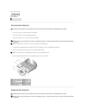
... Before Working on Your Computer. 2. Exercise care when removing and handling the keyboard. NOTICE: The key caps on the keyboard are fragile, easily dislodged, and time- Back to Contents Page Keyboard Dell™ Vostro™ 1710 Service Manual Removing the Keyboard Replacing the Keyboard Removing the Keyboard CAUTION: Before you begin any of the procedures in this section, follow the...
... Before Working on Your Computer. 2. Exercise care when removing and handling the keyboard. NOTICE: The key caps on the keyboard are fragile, easily dislodged, and time- Back to Contents Page Keyboard Dell™ Vostro™ 1710 Service Manual Removing the Keyboard Replacing the Keyboard Removing the Keyboard CAUTION: Before you begin any of the procedures in this section, follow the...
Service Manual
Page 29
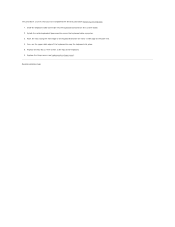
... edge of the palm rest. 4. Back to snap the keyboard into the keyboard connector on the upper right edge of the keyboard. 6. inside edge of the keyboard beneath the front- Replace the hinge cover (see Replacing the Hinge Cover). Rotate the retaining bracket downward to secure the keyboard cable connector. 3. This procedure assumes that you have completed...
... edge of the palm rest. 4. Back to snap the keyboard into the keyboard connector on the upper right edge of the keyboard. 6. inside edge of the keyboard beneath the front- Replace the hinge cover (see Replacing the Hinge Cover). Rotate the retaining bracket downward to secure the keyboard cable connector. 3. This procedure assumes that you have completed...
Service Manual
Page 30
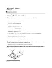
... with Bluetooth® wireless technology to the system board (see Removing the Card). 10. Remove the fan (see Removing the Keyboard). 7. Lift the battery latch assembly out of the button to remove and lift the battery latch assembly over the pin. Remove the... assembly, place the spring in Before Working on Your Computer. 2. Back to Contents Page Battery Latch Assembly Dell™ Vostro™ 1710 Service Manual Removing the Battery Latch Assembly Replacing the Battery Latch Assembly Removing the Battery Latch Assembly CAUTION: Before you remove the battery release button, observe ...
... with Bluetooth® wireless technology to the system board (see Removing the Card). 10. Remove the fan (see Removing the Keyboard). 7. Lift the battery latch assembly out of the button to remove and lift the battery latch assembly over the pin. Remove the... assembly, place the spring in Before Working on Your Computer. 2. Back to Contents Page Battery Latch Assembly Dell™ Vostro™ 1710 Service Manual Removing the Battery Latch Assembly Replacing the Battery Latch Assembly Removing the Battery Latch Assembly CAUTION: Before you remove the battery release button, observe ...
Service Manual
Page 31
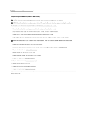
... the internal card with your computer. Connect the cable that you have completed the removal procedure Removing the Battery Latch Assembly. 1. Replace the keyboard (see Replacing a WLAN Card). Replace the WLAN card (see Replacing the Keyboard). 11. Align the guide post on the battery latch assembly with the hole in the battery latch assembly. 4. If you...
... the internal card with your computer. Connect the cable that you have completed the removal procedure Removing the Battery Latch Assembly. 1. Replace the keyboard (see Replacing a WLAN Card). Replace the WLAN card (see Replacing the Keyboard). 11. Align the guide post on the battery latch assembly with the hole in the battery latch assembly. 4. If you...

Service Manual
Page 36
...cable from the optical drive. 9. Remove the WLAN card (see Replacing the Display Assembly). Back to Contents Page Optical Drive Dell™ Vostro™ 1710 Service Manual Removing the Optical Drive Replacing the Optical Drive Removing the Optical Drive CAUTION: Before you begin ...any of the procedures in this section, follow the safety instructions that shipped with your computer. Remove the keyboard (see Removing the Keyboard...
...cable from the optical drive. 9. Remove the WLAN card (see Replacing the Display Assembly). Back to Contents Page Optical Drive Dell™ Vostro™ 1710 Service Manual Removing the Optical Drive Replacing the Optical Drive Removing the Optical Drive CAUTION: Before you begin ...any of the procedures in this section, follow the safety instructions that shipped with your computer. Remove the keyboard (see Removing the Keyboard...

Service Manual
Page 37
Replace the hard drive cover. 5. See Removing the Hard Drive for an illustration of the hard drive cover. Replace the WLAN card (see Replacing the Hinge Cover). 7. Back to Contents Page Replace the hinge cover (see Replacing a WLAN Card). 8. Replace the keyboard (see Replacing the Keyboard). 6.
Replace the hard drive cover. 5. See Removing the Hard Drive for an illustration of the hard drive cover. Replace the WLAN card (see Replacing the Hinge Cover). 7. Back to Contents Page Replace the hinge cover (see Replacing a WLAN Card). 8. Replace the keyboard (see Replacing the Keyboard). 6.
Service Manual
Page 38
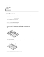
... or blanks installed in the ExpressCard slot and the 8-in Before Working on the palm rest to Contents Page Palm Rest Dell™ Vostro™ 1710 Service Manual Removing the Palm Rest Replacing the Palm Rest Removing the Palm Rest CAUTION: Before you begin the following procedure, follow the safety instructions that secure the... eight M2.5 x 8-mm screws from the fan. Disconnect the multimedia-button pad connector from the image shown below. 9. Remove the hinge cover (see Removing the Keyboard). 7. Remove the keyboard (see Removing the Hinge Cover). 6.
... or blanks installed in the ExpressCard slot and the 8-in Before Working on the palm rest to Contents Page Palm Rest Dell™ Vostro™ 1710 Service Manual Removing the Palm Rest Replacing the Palm Rest Removing the Palm Rest CAUTION: Before you begin the following procedure, follow the safety instructions that secure the... eight M2.5 x 8-mm screws from the fan. Disconnect the multimedia-button pad connector from the image shown below. 9. Remove the hinge cover (see Removing the Keyboard). 7. Remove the keyboard (see Removing the Hinge Cover). 6.


