User Manual
Page 2
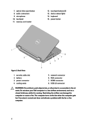
microphone 10. memory card reader 12. power connector 4. cooling vents 5. Do not store your Dell computer in the air vents. touchpad 11. device status lights 14. network connector 6. audio connectors 9. USB 2.0 connector WARNING: Do not block, push objects into, or ...
microphone 10. memory card reader 12. power connector 4. cooling vents 5. Do not store your Dell computer in the air vents. touchpad 11. device status lights 14. network connector 6. audio connectors 9. USB 2.0 connector WARNING: Do not block, push objects into, or ...
User Manual
Page 3
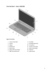
USB 2.0 connectors (2) 8. camera 3. optical drive 6. touchpad 9. memory card reader 12. keyboard 14. touchpad buttons (2) 10. Front And Back - speakers (2) 5. microphone 11. Front View 1. optical drive eject button 7. power button 3 device status lights 13. camera status light 2. Vostro 1540/1550 Figure 3. display 4.
USB 2.0 connectors (2) 8. camera 3. optical drive 6. touchpad 9. memory card reader 12. keyboard 14. touchpad buttons (2) 10. Front And Back - speakers (2) 5. microphone 11. Front View 1. optical drive eject button 7. power button 3 device status lights 13. camera status light 2. Vostro 1540/1550 Figure 3. display 4.
User Manual
Page 6
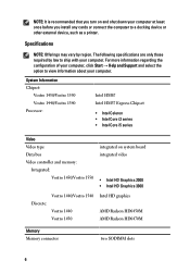
... before you turn on system board integrated video • Intel HD Graphics 2000 • Intel HD Graphics 3000 Discrete: Vostro 1440/Vostro 1540 Vostro 1440 Vostro 1450 Intel HD graphics AMD Radeon HD6450M AMD Radeon HD6470M Memory Memory connector two SODIMM slots 6 NOTE: It is recommended that you install any cards or connect the computer to view...
... before you turn on system board integrated video • Intel HD Graphics 2000 • Intel HD Graphics 3000 Discrete: Vostro 1440/Vostro 1540 Vostro 1440 Vostro 1450 Intel HD graphics AMD Radeon HD6450M AMD Radeon HD6470M Memory Memory connector two SODIMM slots 6 NOTE: It is recommended that you install any cards or connect the computer to view...
User Manual
Page 7
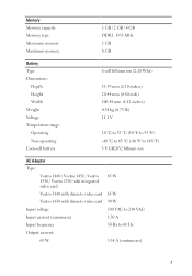
Memory Memory capacity Memory type Minimum memory Maximum memory 1 GB / 2 GB / 4 GB DDR3, 1333 MHz 1 GB 8 GB Battery Type Dimensions: Depth Height Width Weight Voltage Temperature range: Operating Non-operating Coin-cell battery 6-...95 °F) -40 °C to 65 °C (-40 °F to 149 °F) 3 V CR2032 lithium ion AC Adapter Type: Vostro 1440 / Vostro 1450 / Vostro 1540 / Vostro 1550 with integrated video card Vostro 1440 with discrete video card Vostro 1450 with discrete video card Input voltage Input current (maximum) Input frequency Output current: 65 W 65 W 65 W 90 W 100...
Memory Memory capacity Memory type Minimum memory Maximum memory 1 GB / 2 GB / 4 GB DDR3, 1333 MHz 1 GB 8 GB Battery Type Dimensions: Depth Height Width Weight Voltage Temperature range: Operating Non-operating Coin-cell battery 6-...95 °F) -40 °C to 65 °C (-40 °F to 149 °F) 3 V CR2032 lithium ion AC Adapter Type: Vostro 1440 / Vostro 1450 / Vostro 1540 / Vostro 1550 with integrated video card Vostro 1440 with discrete video card Vostro 1450 with discrete video card Input voltage Input current (maximum) Input frequency Output current: 65 W 65 W 65 W 90 W 100...
Owners Manual
Page 3
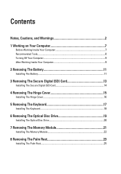
... Hinge Cover 16 5 Removing The Keyboard 17 Installing The Keyboard 18 6 Removing The Optical Disc Drive 19 Installing The Optical Disc Drive 20 7 Removing The Memory Module 21 Installing The Memory Module 22 8 Removing The Palm Rest 23 Installing The Palm Rest 25
... Hinge Cover 16 5 Removing The Keyboard 17 Installing The Keyboard 18 6 Removing The Optical Disc Drive 19 Installing The Optical Disc Drive 20 7 Removing The Memory Module 21 Installing The Memory Module 22 8 Removing The Palm Rest 23 Installing The Palm Rest 25

Owners Manual
Page 13
Slide the memory card out of the computer. 13 Follow the procedures in on the SD memory card to release it from the computer. 3. Press in Before Working On Your Computer. 2. Removing The Secure Digital (SD) Card 3 1.
Slide the memory card out of the computer. 13 Follow the procedures in on the SD memory card to release it from the computer. 3. Press in Before Working On Your Computer. 2. Removing The Secure Digital (SD) Card 3 1.
Owners Manual
Page 14
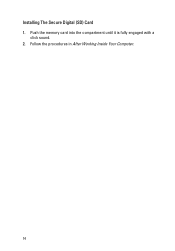
Push the memory card into the compartment until it is fully engaged with a click sound. 2. Follow the procedures in After Working Inside Your Computer. 14 Installing The Secure Digital (SD) Card 1.
Push the memory card into the compartment until it is fully engaged with a click sound. 2. Follow the procedures in After Working Inside Your Computer. 14 Installing The Secure Digital (SD) Card 1.
Owners Manual
Page 21
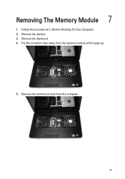
Pry the retention clips away from the computer. 21 Remove the keyboard. 4. Remove the battery. 3. Follow the procedures in Before Working On Your Computer. 2. Remove the memory module from the memory module until it pops up. 5. Removing The Memory Module 7 1.
Pry the retention clips away from the computer. 21 Remove the keyboard. 4. Remove the battery. 3. Follow the procedures in Before Working On Your Computer. 2. Remove the memory module from the memory module until it pops up. 5. Removing The Memory Module 7 1.
Owners Manual
Page 22
Installing The Memory Module 1. Install the battery. 5. Insert the memory module into the memory socket. 2. Install the keyboard. 4. Follow the procedures in place. 3. Press down on the memory module until the retention clips secure the memory module in After Working Inside Your Computer. 22
Installing The Memory Module 1. Install the battery. 5. Insert the memory module into the memory socket. 2. Install the keyboard. 4. Follow the procedures in place. 3. Press down on the memory module until the retention clips secure the memory module in After Working Inside Your Computer. 22
Owners Manual
Page 43
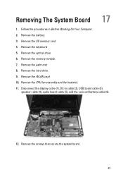
Remove the SD memory card. 4. Remove the palm rest. 8. Follow the procedures in cable (2), USB board cable (3), speaker cable (4), audio board cable (5), and the coin-cell battery cable (6). 12. Remove the hard drive. 9. Remove the CPU fan assembly and the heatsink. 11. Remove the optical drive. 6. Remove the WLAN card. 10. Remove the screws that secure the system board. 43 Disconnect the display cable (1), DC-in Before Working On Your Computer. 2. Remove the keyboard. 5. Remove the memory module. 7. Remove the battery. 3. Removing The System Board 17 1.
Remove the SD memory card. 4. Remove the palm rest. 8. Follow the procedures in cable (2), USB board cable (3), speaker cable (4), audio board cable (5), and the coin-cell battery cable (6). 12. Remove the hard drive. 9. Remove the CPU fan assembly and the heatsink. 11. Remove the optical drive. 6. Remove the WLAN card. 10. Remove the screws that secure the system board. 43 Disconnect the display cable (1), DC-in Before Working On Your Computer. 2. Remove the keyboard. 5. Remove the memory module. 7. Remove the battery. 3. Removing The System Board 17 1.
Owners Manual
Page 45
Install the processor. 5. Install the WLAN card. 7. Install the memory module. 10. Install the SD memory card. 13. Install the CPU fan assembly and the heatsink . 6. Install the battery. 14. Install the screws that secure the system board in cable, USB ...
Install the processor. 5. Install the WLAN card. 7. Install the memory module. 10. Install the SD memory card. 13. Install the CPU fan assembly and the heatsink . 6. Install the battery. 14. Install the screws that secure the system board in cable, USB ...
Owners Manual
Page 47
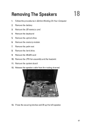
Follow the procedures in Before Working On Your Computer. 2. Remove the memory module. 7. Remove the palm rest. 8. Press the securing latches and lift up the left speaker. 47 Remove the battery. 3. Remove the system board. 12. Remove the keyboard. 5. Remove the hard drive. 9. Remove the SD memory card. 4. Remove the CPU fan assembly and the heatsink. 11. Removing The Speakers 1. Release the speaker cable from the routing channel. 18 13. Remove the optical drive. 6. Remove the WLAN card. 10.
Follow the procedures in Before Working On Your Computer. 2. Remove the memory module. 7. Remove the palm rest. 8. Press the securing latches and lift up the left speaker. 47 Remove the battery. 3. Remove the system board. 12. Remove the keyboard. 5. Remove the hard drive. 9. Remove the SD memory card. 4. Remove the CPU fan assembly and the heatsink. 11. Removing The Speakers 1. Release the speaker cable from the routing channel. 18 13. Remove the optical drive. 6. Remove the WLAN card. 10.
Owners Manual
Page 49
Install the palm rest. 9. Install the optical drive. 11. Follow the procedures in After Working Inside Your Computer. 49 Install the system board. 4. Install the processor. 5. Install the hard drive. 8. Install the SD memory card. 13. Install the CPU fan assembly and the heatsink . 6. Install the WLAN card. 7. Align and route the speaker cable to the chassis. 3. Install the memory module. 10. Install the battery. 14. Insert and attach the left and right speakers into their respective compartments. 2. Install the keyboard. 12. Installing The Speakers 1.
Install the palm rest. 9. Install the optical drive. 11. Follow the procedures in After Working Inside Your Computer. 49 Install the system board. 4. Install the processor. 5. Install the hard drive. 8. Install the SD memory card. 13. Install the CPU fan assembly and the heatsink . 6. Install the WLAN card. 7. Align and route the speaker cable to the chassis. 3. Install the memory module. 10. Install the battery. 14. Insert and attach the left and right speakers into their respective compartments. 2. Install the keyboard. 12. Installing The Speakers 1.

Owners Manual
Page 71
Entering System Setup 25 1. When the blue DELL logo is highlighted, the Options List lists the options that define the hardware installed on (or restart) your computer. • set or change the settings ... information after you are an expert computer user, do not change a user-selectable option such as the user password. • read the current amount of memory or set the type of the System Setup window. Certain changes can appear very quickly, so you must watch for it is recommended that the...
Entering System Setup 25 1. When the blue DELL logo is highlighted, the Options List lists the options that define the hardware installed on (or restart) your computer. • set or change the settings ... information after you are an expert computer user, do not change a user-selectable option such as the user password. • read the current amount of memory or set the type of the System Setup window. Certain changes can appear very quickly, so you must watch for it is recommended that the...

Owners Manual
Page 73
...Product Name Service Tag Asset Tag CPU Type CPU Speed CPU ID L1 Cache Size L2 Cache Size L3 Cache Size Extended Memory System Memory Memory Speed Fixed HDD SATA ODD AC Adapter Type Advanced Intel SpeedStep Virtualization Integrated NIC Re-sets the time on the computer. Displays... feature. Enable or disable the Intel Default: Enabled SpeedStep feature. Displays the asset tag of the optical drive. Displays the memory installed on the computer's internal clock. Displays the type of the processor. Displays the model number and capacity of your computer. Displays ...
...Product Name Service Tag Asset Tag CPU Type CPU Speed CPU ID L1 Cache Size L2 Cache Size L3 Cache Size Extended Memory System Memory Memory Speed Fixed HDD SATA ODD AC Adapter Type Advanced Intel SpeedStep Virtualization Integrated NIC Re-sets the time on the computer. Displays... feature. Enable or disable the Intel Default: Enabled SpeedStep feature. Displays the asset tag of the optical drive. Displays the memory installed on the computer's internal clock. Displays the type of the processor. Displays the model number and capacity of your computer. Displays ...
Owners Manual
Page 77
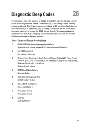
... and Troubleshooting Steps 1 BIOS ROM checksum in progress or failure System board failure, covers BIOS corruption or ROM error 2 No RAM detected No memory detected 3 Chipset Error (North and South Bridge Chipset, DMA/IMR/ Timer Error) , Time-Of-Day Clock test failure , Gate A20 failure... , Super I/O chip failure , Keyboard controller test failure System board failure 4 RAM Read/Write failure Memory failure 5 Real-time clock power fail CMOS battery failure 6 Video BIOS test failure Video card failure 7 Processor failure Processor failure 8 Display Display...
... and Troubleshooting Steps 1 BIOS ROM checksum in progress or failure System board failure, covers BIOS corruption or ROM error 2 No RAM detected No memory detected 3 Chipset Error (North and South Bridge Chipset, DMA/IMR/ Timer Error) , Time-Of-Day Clock test failure , Gate A20 failure... , Super I/O chip failure , Keyboard controller test failure System board failure 4 RAM Read/Write failure Memory failure 5 Real-time clock power fail CMOS battery failure 6 Video BIOS test failure Video card failure 7 Processor failure Processor failure 8 Display Display...
Owners Manual
Page 79
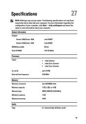
... Support and select the option to 6 MB 1333 MHz Memory Memory connector Memory capacity Memory type Minimum memory Maximum memory two SODIMM slots 1 GB, 2 GB, or 4 GB DDR3 SDRAM (1333 MHz) 1 GB 8 GB Audio Type 2.1 channel high definition audio 79 System Information Chipset Vostro 1450/Vostro 1550 Vostro 1440/Vostro 1540 DRAM bus width Flash EPROM Intel HM67 Intel HM57 64...
... Support and select the option to 6 MB 1333 MHz Memory Memory connector Memory capacity Memory type Minimum memory Maximum memory two SODIMM slots 1 GB, 2 GB, or 4 GB DDR3 SDRAM (1333 MHz) 1 GB 8 GB Audio Type 2.1 channel high definition audio 79 System Information Chipset Vostro 1450/Vostro 1550 Vostro 1440/Vostro 1540 DRAM bus width Flash EPROM Intel HM67 Intel HM57 64...


