Setup and Features Information Tech Sheet
Page 1
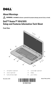
About Warnings WARNING: A WARNING indicates a potential for property damage, personal injury, or death. Dell™ Vostro™ 1014/1015 Setup and Features Information Tech Sheet Front View 123 4 17 16 15 14 13 1 microphone (optional) 3 camera (optional) 5 keyboard status lights November 2010 5 6 9 87 12 11 10 2 camera light (optional) 4 display 6 power button Models: PP38L and PP37L
About Warnings WARNING: A WARNING indicates a potential for property damage, personal injury, or death. Dell™ Vostro™ 1014/1015 Setup and Features Information Tech Sheet Front View 123 4 17 16 15 14 13 1 microphone (optional) 3 camera (optional) 5 keyboard status lights November 2010 5 6 9 87 12 11 10 2 camera light (optional) 4 display 6 power button Models: PP38L and PP37L

Setup and Features Information Tech Sheet
Page 4
... device or other external device, such as a printer. For more information regarding the configuration of memory for balanced graphics and system performance. 5 Open the computer display and press the power button to view information about your computer. The following specifications are only those required by allocating the optimum amount of your...
... device or other external device, such as a printer. For more information regarding the configuration of memory for balanced graphics and system performance. 5 Open the computer display and press the power button to view information about your computer. The following specifications are only those required by allocating the optimum amount of your...
Service Manual
Page 6
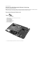
... Remove the keyboard. 8. Remove the display assembly. 9. Disconnect the Bluetooth card cable from the connector on the system board. For additional safety best practices information, see the Regulatory Compliance Homepage at www.dell.com/regulatory_compliance. Follow the procedures in Before...Bluetooth Wireless Card 1. Remove the battery. 3. Back to Contents Page Internal Card With Bluetooth® Wireless Technology Dell™ Vostro™ 1014/1015 Service Manual WARNING: Before working inside your computer, read the safety information that shipped with your computer. Remove ...
... Remove the keyboard. 8. Remove the display assembly. 9. Disconnect the Bluetooth card cable from the connector on the system board. For additional safety best practices information, see the Regulatory Compliance Homepage at www.dell.com/regulatory_compliance. Follow the procedures in Before...Bluetooth Wireless Card 1. Remove the battery. 3. Back to Contents Page Internal Card With Bluetooth® Wireless Technology Dell™ Vostro™ 1014/1015 Service Manual WARNING: Before working inside your computer, read the safety information that shipped with your computer. Remove ...
Service Manual
Page 8
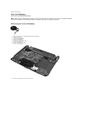
... coin-cell battery from the plastic sleeve. Remove the access panel. 4. Remove the display assembly. 9. Follow the procedures in Before Working Inside Your Computer. 2. Remove the battery. 3. Back to Contents Page Coin-Cell Battery Dell™ Vostro™ 1014/1015 Service Manual WARNING: Before working inside your computer, read the safety information that shipped...
... coin-cell battery from the plastic sleeve. Remove the access panel. 4. Remove the display assembly. 9. Follow the procedures in Before Working Inside Your Computer. 2. Remove the battery. 3. Back to Contents Page Coin-Cell Battery Dell™ Vostro™ 1014/1015 Service Manual WARNING: Before working inside your computer, read the safety information that shipped...
Service Manual
Page 11
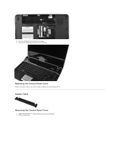
Replacing the Control Panel Cover Perform the above steps in Before Working Inside Your Computer. 2. Remove the battery. 5. Vostro 1015 Removing the Control Panel Cover 1. Remove the control panel cover from the computer. Turn the computer over and open the display. 6. Follow the procedures in the reverse order to replace the control panel cover.
Replacing the Control Panel Cover Perform the above steps in Before Working Inside Your Computer. 2. Remove the battery. 5. Vostro 1015 Removing the Control Panel Cover 1. Remove the control panel cover from the computer. Turn the computer over and open the display. 6. Follow the procedures in the reverse order to replace the control panel cover.

Service Manual
Page 12
Remove the eight control panel cover screws from the computer. Replacing the Control Panel Cover Remove the control panel cover from the bottom of the computer. 4. Turn the computer over and open the display. 5. 3.
Remove the eight control panel cover screws from the computer. Replacing the Control Panel Cover Remove the control panel cover from the bottom of the computer. 4. Turn the computer over and open the display. 5. 3.
Service Manual
Page 14
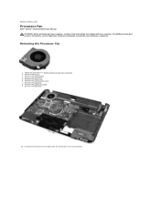
... cable from the connector on the system board. Remove the WLAN card. 6. Remove the display assembly. 9. For additional safety best practices information, see the Regulatory Compliance Homepage at www.dell.com/regulatory_compliance. Remove the battery. 3. Remove the palm rest. 10. Removing the Processor ... the procedures in Before Working Inside Your Computer. 2. Remove the keyboard. 8. Back to Contents Page Processor Fan Dell™ Vostro™ 1014/1015 Service Manual WARNING: Before working inside your computer, read the safety information that shipped with your computer.
... cable from the connector on the system board. Remove the WLAN card. 6. Remove the display assembly. 9. For additional safety best practices information, see the Regulatory Compliance Homepage at www.dell.com/regulatory_compliance. Remove the battery. 3. Remove the palm rest. 10. Removing the Processor ... the procedures in Before Working Inside Your Computer. 2. Remove the keyboard. 8. Back to Contents Page Processor Fan Dell™ Vostro™ 1014/1015 Service Manual WARNING: Before working inside your computer, read the safety information that shipped with your computer.
Service Manual
Page 23
...display assembly. 12. Remove the control panel cover. 10. Remove the Bluetooth wireless card. 16. Follow the procedures in the illustration below to loosen the four screws that shipped with your computer, read the safety information that secure the heat sink to Contents Page Heat Sink Dell™ Vostro™ 1014/1015... (if applicable). 3. For additional safety best practices information, see the Regulatory Compliance Homepage at www.dell.com/regulatory_compliance. Remove the keyboard. 11. Back to the system board. Use the marked sequence in Before Working Inside Your...
...display assembly. 12. Remove the control panel cover. 10. Remove the Bluetooth wireless card. 16. Follow the procedures in the illustration below to loosen the four screws that shipped with your computer, read the safety information that secure the heat sink to Contents Page Heat Sink Dell™ Vostro™ 1014/1015... (if applicable). 3. For additional safety best practices information, see the Regulatory Compliance Homepage at www.dell.com/regulatory_compliance. Remove the keyboard. 11. Back to the system board. Use the marked sequence in Before Working Inside Your...

Service Manual
Page 25
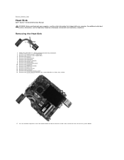
... the control panel cover. 7. Remove the keyboard. 8. Removing the I /O board to Contents Page I/O Board Dell™ Vostro™ 1014/1015 Service Manual WARNING: Before working inside your computer, read the safety information that secure the I /O Board 1. Remove the display assembly. 9. Follow the procedures in Before Working Inside Your Computer. 2. For additional safety best practices...
... the control panel cover. 7. Remove the keyboard. 8. Removing the I /O board to Contents Page I/O Board Dell™ Vostro™ 1014/1015 Service Manual WARNING: Before working inside your computer, read the safety information that secure the I /O Board 1. Remove the display assembly. 9. Follow the procedures in Before Working Inside Your Computer. 2. For additional safety best practices...
Service Manual
Page 30
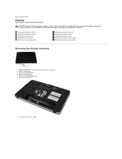
.... 7. Remove the battery. 3. Disconnect the wireless cables. Follow the procedures in Before Working Inside Your Computer. 2. Remove the keyboard. 8. Back to Contents Page Display Dell™ Vostro™ 1014/1015 Service Manual WARNING: Before working inside your computer, read the safety information that shipped with your computer. For additional safety best practices information, see...
.... 7. Remove the battery. 3. Disconnect the wireless cables. Follow the procedures in Before Working Inside Your Computer. 2. Remove the keyboard. 8. Back to Contents Page Display Dell™ Vostro™ 1014/1015 Service Manual WARNING: Before working inside your computer, read the safety information that shipped with your computer. For additional safety best practices information, see...

Service Manual
Page 31
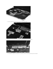
Remove the two screws that secure the display assembly to the bottom of the base of the computer. 10. Turn the computer right-side up and open the display. 11. Remove the wireless cable from the routing guides. 9.
Remove the two screws that secure the display assembly to the bottom of the base of the computer. 10. Turn the computer right-side up and open the display. 11. Remove the wireless cable from the routing guides. 9.
Service Manual
Page 32
Ensure that secure the display assembly to disconnect the display inverter cable. 13. Lift the display assembly from the computer. Remove the two screws that all the cables are carefully removed away from the computer. 12. Rotate the display inverter cable clip to the top of the base of the computer. 14.
Ensure that secure the display assembly to disconnect the display inverter cable. 13. Lift the display assembly from the computer. Remove the two screws that all the cables are carefully removed away from the computer. 12. Rotate the display inverter cable clip to the top of the base of the computer. 14.
Service Manual
Page 33
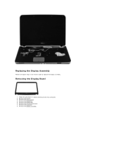
Removing the Display Bezel 1. Remove the hard drive. 5. Remove the WLAN card. 6. Remove the access panel. 4. Remove the battery. 3. Remove the display assembly. Follow the procedures in the reverse order to replace the display assembly. Remove the keyboard. 8. Remove the control panel cover. 7. Replacing the Display Assembly Perform the above steps in Before Working Inside Your Computer. 2.
Removing the Display Bezel 1. Remove the hard drive. 5. Remove the WLAN card. 6. Remove the access panel. 4. Remove the battery. 3. Remove the display assembly. Follow the procedures in the reverse order to replace the display assembly. Remove the keyboard. 8. Remove the control panel cover. 7. Replacing the Display Assembly Perform the above steps in Before Working Inside Your Computer. 2.

Service Manual
Page 34
Remove the six screws from the display assembly. 10. 9. Using a plastic scribe, remove the six rubber screw covers from the display assembly.
Remove the six screws from the display assembly. 10. 9. Using a plastic scribe, remove the six rubber screw covers from the display assembly.

Service Manual
Page 35
Removing the Display LED Panel 1. Remove the hard drive. 5. Remove the keyboard. Remove the display bezel. Follow the procedures in the reverse order to replace the display bezel into the display assembly. Remove the access panel. 4. Replacing the Display Bezel Perform the above steps in Before Working Inside Your Computer. 2. Remove the battery. 3. Remove the control panel cover. 7. 11. Remove the WLAN card. 6.
Removing the Display LED Panel 1. Remove the hard drive. 5. Remove the keyboard. Remove the display bezel. Follow the procedures in the reverse order to replace the display bezel into the display assembly. Remove the access panel. 4. Replacing the Display Bezel Perform the above steps in Before Working Inside Your Computer. 2. Remove the battery. 3. Remove the control panel cover. 7. 11. Remove the WLAN card. 6.

Service Manual
Page 36
8. Remove the display assembly. 9. Remove the display bezel. 10. Remove the four screws that secure the display panel to the display assembly. 11. Disconnect the display camera cable.
8. Remove the display assembly. 9. Remove the display bezel. 10. Remove the four screws that secure the display panel to the display assembly. 11. Disconnect the display camera cable.

Service Manual
Page 37
Lift the display LED panel from the display assembly. Follow the procedures in the reverse to replace the display LED panel. Remove the display assembly. 9. Replacing the Display LED Panel Perform the above steps in Before Working Inside Your Computer. 2. Removing the Display Camera 1. Remove the control panel cover. 7. Remove the keyboard. 8. Remove the hard drive. 5. 12. Remove the WLAN card. 6. Remove the access panel. 4. Remove the display LED panel. Remove the battery. 3. Remove the display bezel. 10.
Lift the display LED panel from the display assembly. Follow the procedures in the reverse to replace the display LED panel. Remove the display assembly. 9. Replacing the Display LED Panel Perform the above steps in Before Working Inside Your Computer. 2. Removing the Display Camera 1. Remove the control panel cover. 7. Remove the keyboard. 8. Remove the hard drive. 5. 12. Remove the WLAN card. 6. Remove the access panel. 4. Remove the display LED panel. Remove the battery. 3. Remove the display bezel. 10.

Service Manual
Page 38
... two screws that secure the display camera to the display assembly. Removing the Display Inverter Cable 1. Remove the hard drive. 5. Remove the display bezel. 10. Remove the battery. 3. Remove the control panel cover. 7. Remove the display LED panel. Lift the display camera from there to the display assembly. 12. Replacing the Display Camera Perform the above steps in...
... two screws that secure the display camera to the display assembly. Removing the Display Inverter Cable 1. Remove the hard drive. 5. Remove the display bezel. 10. Remove the battery. 3. Remove the control panel cover. 7. Remove the display LED panel. Lift the display camera from there to the display assembly. 12. Replacing the Display Camera Perform the above steps in...

Service Manual
Page 39
Replacing the Display Inverter Cable Perform the above steps in the reverse order to the display LED panel. 12. Remove the two screws that secure the display camera to replace the display inverter cable. Carefully detach and remove the display inverter cable from the display LED panel. Back to Contents Page 11.
Replacing the Display Inverter Cable Perform the above steps in the reverse order to the display LED panel. 12. Remove the two screws that secure the display camera to replace the display inverter cable. Carefully detach and remove the display inverter cable from the display LED panel. Back to Contents Page 11.
Service Manual
Page 40
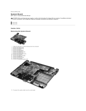
Vostro 1014 Vostro 1015 Vostro 1014 Removing the System Board 1. Remove the memory card. 4. Remove the battery. 5. Remove the palm rest. 13. Remove the Bluetooth wireless card. 16. Remove the memory modules. 8. Remove the display assembly. 12. Remove the ExpressCard. 3. Remove the WLAN card. 9. ... information, see the Regulatory Compliance Homepage at www.dell.com/regulatory_compliance. Remove the hard drive. 7. Remove the processor fan. 14. Back to Contents Page System Board Dell™ Vostro™ 1014/1015 Service Manual WARNING: Before working inside your computer,...
Vostro 1014 Vostro 1015 Vostro 1014 Removing the System Board 1. Remove the memory card. 4. Remove the battery. 5. Remove the palm rest. 13. Remove the Bluetooth wireless card. 16. Remove the memory modules. 8. Remove the display assembly. 12. Remove the ExpressCard. 3. Remove the WLAN card. 9. ... information, see the Regulatory Compliance Homepage at www.dell.com/regulatory_compliance. Remove the hard drive. 7. Remove the processor fan. 14. Back to Contents Page System Board Dell™ Vostro™ 1014/1015 Service Manual WARNING: Before working inside your computer,...


