Owner's Manual
Page 29
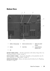
... in the optical drive bay. Bottom View 12 3 4 5 7 6 1 battery charge gauge 2 device security screw 3 battery-bay latch release 4 battery 5 hard drive 6 modem/memory module cover 7 fan B A T T E R Y C H A R G E G A U G E - See "Replacing the Battery" on page 92. Provides information on page 54. Releases the battery from the battery bay. D E V I C E S E C U R I T Y S C R E W - See "Checking the Battery Charge" on the...
... in the optical drive bay. Bottom View 12 3 4 5 7 6 1 battery charge gauge 2 device security screw 3 battery-bay latch release 4 battery 5 hard drive 6 modem/memory module cover 7 fan B A T T E R Y C H A R G E G A U G E - See "Replacing the Battery" on page 92. Provides information on page 54. Releases the battery from the battery bay. D E V I C E S E C U R I T Y S C R E W - See "Checking the Battery Charge" on the...

Owner's Manual
Page 205
...Mobile Broadband, 69 removing, 71 slots, 69 types, 69 WWAN, 69 H hard drive description, 26, 30 problems, 120 replacing, 92 returning to Dell, 94 hardware Dell Diagnostics, 111 Hardware Troubleshooter, 147 Help and Support Center, 17 help file Windows Help and Support Center, 17 hibernate mode, ...57 hinge cover removing, 100 F fan description, 25, 30 Files and Settings Transfer Wizard, 33 firewall Windows XP, 83 floppy ...
...Mobile Broadband, 69 removing, 71 slots, 69 types, 69 WWAN, 69 H hard drive description, 26, 30 problems, 120 replacing, 92 returning to Dell, 94 hardware Dell Diagnostics, 111 Hardware Troubleshooter, 147 Help and Support Center, 17 help file Windows Help and Support Center, 17 hibernate mode, ...57 hinge cover removing, 100 F fan description, 25, 30 Files and Settings Transfer Wizard, 33 firewall Windows XP, 83 floppy ...
Service Manual
Page 21
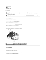
....5 x 5-mm screws from the connector on the system board. 1 fan 4 fan system board connector 2 M2.5 x 5-mm screws (2) 3 fan cable connector Replacing a Fan 1. Replace the two M2.5 x 5-mm screws in Before You Begin. 2. Connect the fan connector to Contents Page Fan Dell™ Latitude™ 131L/ Dell Vostro™ 1000 Service Manual Removing a Fan Replacing a Fan CAUTION: Before you begin the following procedure, follow the safety...
....5 x 5-mm screws from the connector on the system board. 1 fan 4 fan system board connector 2 M2.5 x 5-mm screws (2) 3 fan cable connector Replacing a Fan 1. Replace the two M2.5 x 5-mm screws in Before You Begin. 2. Connect the fan connector to Contents Page Fan Dell™ Latitude™ 131L/ Dell Vostro™ 1000 Service Manual Removing a Fan Replacing a Fan CAUTION: Before you begin the following procedure, follow the safety...
Service Manual
Page 42
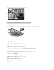
Back to Contents Page System Board Dell™ Latitude™ 131L/ Dell Vostro™ 1000 Service Manual Removing the System Board Replacing the System Board CAUTION: Before you remove the fan. 11. Remove the hard drive (see Removing the Display Assembly). 10. Remove the display assembly (see Removing the Hard Drive). 3. Remove the processor thermal-cooling ...
Back to Contents Page System Board Dell™ Latitude™ 131L/ Dell Vostro™ 1000 Service Manual Removing the System Board Replacing the System Board CAUTION: Before you remove the fan. 11. Remove the hard drive (see Removing the Display Assembly). 10. Remove the display assembly (see Removing the Hard Drive). 3. Remove the processor thermal-cooling ...
Service Manual
Page 43
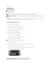
... computer to release the connectors on the system board from the system board. 1 M2.5 x 5-mm screws (2) 17. Replace the Mini-Card (see Replacing the Hinge Cover). 16. Replace the fan (see Replacing the Palm Rest). 9. Replacing the System Board 1. Replace the palm rest (see Replacing a Fan). 8. Replace the ExpressCard/hard-drive bay assembly (see Replacing the ExpressCard/Hard-Drive Bay Assembly). 5.
... computer to release the connectors on the system board from the system board. 1 M2.5 x 5-mm screws (2) 17. Replace the Mini-Card (see Replacing the Hinge Cover). 16. Replace the fan (see Replacing the Palm Rest). 9. Replacing the System Board 1. Replace the palm rest (see Replacing a Fan). 8. Replace the ExpressCard/hard-drive bay assembly (see Replacing the ExpressCard/Hard-Drive Bay Assembly). 5.


