
Owner's Manual
Page 8
...or Mouse Problems 97 Video and Display Problems 98 If the display is blank 98 If the display is difficult to read 99 If only part of the display is readable 99 Drivers 100 What Is a Driver 100 Identifying Drivers 100 Reinstalling Drivers and Utilities 100 Troubleshooting Software and ... Operating System 103 Using Microsoft Windows System Restore . . . . 103 Starting System Restore 104 Using the Operating System Media 105 11 Adding and Replacing Parts 107 Before You Begin 107 Recommended Tools 107 Turning Off Your Computer 107 Before Working Inside Your Computer 108 8 Contents
...or Mouse Problems 97 Video and Display Problems 98 If the display is blank 98 If the display is difficult to read 99 If only part of the display is readable 99 Drivers 100 What Is a Driver 100 Identifying Drivers 100 Reinstalling Drivers and Utilities 100 Troubleshooting Software and ... Operating System 103 Using Microsoft Windows System Restore . . . . 103 Starting System Restore 104 Using the Operating System Media 105 11 Adding and Replacing Parts 107 Before You Begin 107 Recommended Tools 107 Turning Off Your Computer 107 Before Working Inside Your Computer 108 8 Contents

Owner's Manual
Page 78
... to increase the possibility of common symptoms and allows you select Test System to 20 minutes and requires no interaction on your part. When contacting Dell support, have selected the Test System option from the menu below to run . Option Test Memory Test System Exit Function Run... the stand-alone memory test Run System Diagnostics Exit Diagnostics After you cannot resolve the problem, contact Dell (see "Contacting Dell" on the screen. The test typically takes an hour or more thorough check of the problem you want to answer specific questions...
... to increase the possibility of common symptoms and allows you select Test System to 20 minutes and requires no interaction on your part. When contacting Dell support, have selected the Test System option from the menu below to run . Option Test Memory Test System Exit Function Run... the stand-alone memory test Run System Diagnostics Exit Diagnostics After you cannot resolve the problem, contact Dell (see "Contacting Dell" on the screen. The test typically takes an hour or more thorough check of the problem you want to answer specific questions...
Owner's Manual
Page 99
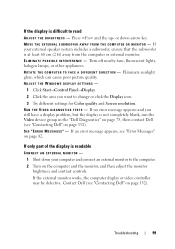
...to the computer. 2 Turn on page 132). If only part of the display is not completely blank, run the Video device group in the "Dell Diagnostics" on page 75, then contact Dell (see "Contacting Dell" on the computer and the monitor, and then adjust ... display is readable CONNECT AN EXTERNAL MONITOR - 1 Shut down -arrow key. Contact Dell (see "Error Messages" on page 132). R U N T H E VI D E O D I A G N O S T I N T E R F E R E N C E - SEE "ERROR M ESSAGES" - If an error message appears, see "Contacting Dell" on page 82. Troubleshooting 99 If the display is at least 60 cm (2...
...to the computer. 2 Turn on page 132). If only part of the display is not completely blank, run the Video device group in the "Dell Diagnostics" on page 75, then contact Dell (see "Contacting Dell" on the computer and the monitor, and then adjust ... display is readable CONNECT AN EXTERNAL MONITOR - 1 Shut down -arrow key. Contact Dell (see "Error Messages" on page 132). R U N T H E VI D E O D I A G N O S T I N T E R F E R E N C E - SEE "ERROR M ESSAGES" - If an error message appears, see "Contacting Dell" on page 82. Troubleshooting 99 If the display is at least 60 cm (2...

Owner's Manual
Page 107
... system shutdown process is complete. Recommended Tools The procedures in reverse order. The computer turns off your computer. Adding and Replacing Parts 107 Unless otherwise noted, each procedure assumes that the following conditions exist: • You have performed the steps in "Turning Off... • Small flat-blade screwdriver • Phillips screwdriver • Small plastic scribe • Flash BIOS update (see the Dell Support website at support.dell.com) Turning Off Your Computer NOTICE: To avoid losing data, save and close any open files and exit any open programs....
... system shutdown process is complete. Recommended Tools The procedures in reverse order. The computer turns off your computer. Adding and Replacing Parts 107 Unless otherwise noted, each procedure assumes that the following conditions exist: • You have performed the steps in "Turning Off... • Small flat-blade screwdriver • Phillips screwdriver • Small plastic scribe • Flash BIOS update (see the Dell Support website at support.dell.com) Turning Off Your Computer NOTICE: To avoid losing data, save and close any open files and exit any open programs....

Owner's Manual
Page 108
... your computer from potential damage and to servicing that is not authorized by its edges or by Dell is flat and clean to prevent the computer cover from their electrical outlets. 108 Adding and Replacing Parts Hold a component such as a connector on page 107). CAUTION: Handle components and cards with locking tabs...
... your computer from potential damage and to servicing that is not authorized by its edges or by Dell is flat and clean to prevent the computer cover from their electrical outlets. 108 Adding and Replacing Parts Hold a component such as a connector on page 107). CAUTION: Handle components and cards with locking tabs...

Owner's Manual
Page 109
... latch toward the side of the computer until it is hot, do not touch the metal housing of the procedures in this particular Dell computer. Adding and Replacing Parts 109 NOTICE: To help prevent damage to the system board, you must remove the battery from the battery bay before you begin any...
... latch toward the side of the computer until it is hot, do not touch the metal housing of the procedures in this particular Dell computer. Adding and Replacing Parts 109 NOTICE: To help prevent damage to the system board, you must remove the battery from the battery bay before you begin any...

Owner's Manual
Page 110
...from a source other than Dell, you are extremely fragile. Removing the Hard Drive 1 Follow the procedures in "Before You Begin" on or in the Product Information Guide). 3 Slide the hard drive out of the computer. 110 Adding and Replacing Parts Do not remove the hard... antistatic packaging (see "Protecting Against Electrostatic Discharge" in Sleep state. NOTICE: Hard drives are installing a hard drive from sources other than Dell. NOTE: If you need to install an operating system, drivers, and utilities on the new hard drive (see "Restoring Your Operating System...
...from a source other than Dell, you are extremely fragile. Removing the Hard Drive 1 Follow the procedures in "Before You Begin" on or in the Product Information Guide). 3 Slide the hard drive out of the computer. 110 Adding and Replacing Parts Do not remove the hard... antistatic packaging (see "Protecting Against Electrostatic Discharge" in Sleep state. NOTICE: Hard drives are installing a hard drive from sources other than Dell. NOTE: If you need to install an operating system, drivers, and utilities on the new hard drive (see "Restoring Your Operating System...

Owner's Manual
Page 111
NOTICE: Use firm and even pressure to Dell in transit. 2 1 1 foam packaging 2 hard drive Adding and Replacing Parts 111 Returning a Hard Drive to Dell Return your old hard drive to slide the drive into the bay until it is fully seated. 3 Replace and tighten the two screws. 4 Install the ...
NOTICE: Use firm and even pressure to Dell in transit. 2 1 1 foam packaging 2 hard drive Adding and Replacing Parts 111 Returning a Hard Drive to Dell Return your old hard drive to slide the drive into the bay until it is fully seated. 3 Replace and tighten the two screws. 4 Install the ...

Owner's Manual
Page 112
... drive 2 locking screw Replacing the Optical Drive 1 Slide the optical drive into the bay. 2 Replace and tighten the locking screw. 3 notch 112 Adding and Replacing Parts
... drive 2 locking screw Replacing the Optical Drive 1 Slide the optical drive into the bay. 2 Replace and tighten the locking screw. 3 notch 112 Adding and Replacing Parts

Owner's Manual
Page 113
... scribe into the indent to lift the hinge cover on page 107. 2 Open the display as far as it . 1 2 1 hinge cover 2 scribe Adding and Replacing Parts 113 NOTICE: To help prevent damage to left, and remove it will open.
... scribe into the indent to lift the hinge cover on page 107. 2 Open the display as far as it . 1 2 1 hinge cover 2 scribe Adding and Replacing Parts 113 NOTICE: To help prevent damage to left, and remove it will open.

Owner's Manual
Page 114
... (see "Using the Keyboard and Touch Pad" on page 41. NOTICE: The key caps on the back of the keyboard connector. 114 Adding and Replacing Parts Keyboard For more information about the keyboard, see "Hinge Cover" on the system board, rotate the keyboard connector latch toward the front of the computer...
... (see "Using the Keyboard and Touch Pad" on page 41. NOTICE: The key caps on the back of the keyboard connector. 114 Adding and Replacing Parts Keyboard For more information about the keyboard, see "Hinge Cover" on the system board, rotate the keyboard connector latch toward the front of the computer...

Owner's Manual
Page 115
Adding and Replacing Parts 115 1 2 3 4 5 1 screws (2) 3 keyboard tabs (5) 5 keyboard connector latch 2 keyboard 4 keyboard cable Replacing the Keyboard 1 Slide the keyboard cable into the keyboard connector. 2 Rotate the keyboard connector latch to secure the cable. 3 Hook the tabs along the front edge of the keyboard into the palmrest. 4 Press on the right edge near the top to snap the keyboard into place. 5 Replace the two screws on the top of the keyboard.
Adding and Replacing Parts 115 1 2 3 4 5 1 screws (2) 3 keyboard tabs (5) 5 keyboard connector latch 2 keyboard 4 keyboard cable Replacing the Keyboard 1 Slide the keyboard cable into the keyboard connector. 2 Rotate the keyboard connector latch to secure the cable. 3 Hook the tabs along the front edge of the keyboard into the palmrest. 4 Press on the right edge near the top to snap the keyboard into place. 5 Replace the two screws on the top of the keyboard.

Owner's Manual
Page 116
... The memory modules are intended for information on the system board. Your computer has two user-accessible SODIMM sockets, DIMM A and DIMM B, accessed from Dell are covered under the memory module cover on the bottom of the computer. 1 Follow the procedures in "Before You Begin" on page 107. 2 ...down, loosen the eight captive screws on the cover (see "Bottom View" on page 28), and remove the cover. 116 Adding and Replacing Parts Memory CAUTION: Before you install a module in the Product Information Guide. NOTE: Memory modules purchased from the bottom of the computer.
... The memory modules are intended for information on the system board. Your computer has two user-accessible SODIMM sockets, DIMM A and DIMM B, accessed from Dell are covered under the memory module cover on the bottom of the computer. 1 Follow the procedures in "Before You Begin" on page 107. 2 ...down, loosen the eight captive screws on the cover (see "Bottom View" on page 28), and remove the cover. 116 Adding and Replacing Parts Memory CAUTION: Before you install a module in the Product Information Guide. NOTE: Memory modules purchased from the bottom of the computer.

Owner's Manual
Page 117
1 2 1 cover 2 captive screws (8) NOTICE: To prevent damage to the memory module connector, do not use tools to carefully spread apart the securing clips on the back of the computer). 3 Use your fingertips to spread the memory module securing clips. Adding and Replacing Parts 117 NOTICE: To avoid electrostatic discharge, ground yourself by using a wrist grounding strap or by periodically touching an unpainted metal surface (such as a connector on each end of the memory module connector until the module pops up. 4 Remove the module from the connector.
1 2 1 cover 2 captive screws (8) NOTICE: To prevent damage to the memory module connector, do not use tools to carefully spread apart the securing clips on the back of the computer). 3 Use your fingertips to spread the memory module securing clips. Adding and Replacing Parts 117 NOTICE: To avoid electrostatic discharge, ground yourself by using a wrist grounding strap or by periodically touching an unpainted metal surface (such as a connector on each end of the memory module connector until the module pops up. 4 Remove the module from the connector.

Owner's Manual
Page 118
... you do not feel the click, remove the module and reinstall it clicks into place. No error message indicates this failure. 118 Adding and Replacing Parts 1 2 1 securing clips (2) 2 memory module Replacing Memory Module NOTICE: To avoid electrostatic discharge, ground yourself by using a wrist grounding strap or by periodically touching an unpainted...
... you do not feel the click, remove the module and reinstall it clicks into place. No error message indicates this failure. 118 Adding and Replacing Parts 1 2 1 securing clips (2) 2 memory module Replacing Memory Module NOTICE: To avoid electrostatic discharge, ground yourself by using a wrist grounding strap or by periodically touching an unpainted...

Owner's Manual
Page 119
Adding and Replacing Parts 119 Forcing the cover to close , remove the module and reinstall it detects the additional memory and automatically updates the system configuration information. As the ...
Adding and Replacing Parts 119 Forcing the cover to close , remove the module and reinstall it detects the additional memory and automatically updates the system configuration information. As the ...

Owner's Manual
Page 120
... page 107. 2 Turn the computer over. 3 Loosen the eight captive screws securing the cover and remove the cover. 1 2 1 cover 2 captive screws (8) 120 Adding and Replacing Parts Wireless Mini-Cards CAUTION: Before you begin working inside the computer.
... page 107. 2 Turn the computer over. 3 Loosen the eight captive screws securing the cover and remove the cover. 1 2 1 cover 2 captive screws (8) 120 Adding and Replacing Parts Wireless Mini-Cards CAUTION: Before you begin working inside the computer.

Owner's Manual
Page 121
NOTE: The Mini-card may have two or three connectors, depending on the type of card you ordered. 2 1 1 antenna cable connectors 2 securing screw 5 Release the Mini-card by removing the securing screw. 6 Lift the card out of its system board connector. 1 1 Mini-Card Adding and Replacing Parts 121 4 Disconnect the antenna cables from the Mini-card.
NOTE: The Mini-card may have two or three connectors, depending on the type of card you ordered. 2 1 1 antenna cable connectors 2 securing screw 5 Release the Mini-card by removing the securing screw. 6 Lift the card out of its system board connector. 1 1 Mini-Card Adding and Replacing Parts 121 4 Disconnect the antenna cables from the Mini-card.

Owner's Manual
Page 122
... installed. NOTE: For more specific information about which connector, see "Hinge Cover" on page 113). 3 Remove the screw securing the card. 122 Adding and Replacing Parts NOTICE: To avoid damage to which cable to connect to the Mini-card, never place cables under the card. 1 Insert the card connector into the...
... installed. NOTE: For more specific information about which connector, see "Hinge Cover" on page 113). 3 Remove the screw securing the card. 122 Adding and Replacing Parts NOTICE: To avoid damage to which cable to connect to the Mini-card, never place cables under the card. 1 Insert the card connector into the...

Owner's Manual
Page 123
Adding and Replacing Parts 123 4 Grasp the connector end of the card and slide it out from under the securing tabs. 5 Disconnect the cable from the card. 1 2 1 securing screw 2 card Replacing the Card 1 Replace the screw securing the card and insert the card at an angle to slide it in the card compartment. 2 Connect the cable to the card.
Adding and Replacing Parts 123 4 Grasp the connector end of the card and slide it out from under the securing tabs. 5 Disconnect the cable from the card. 1 2 1 securing screw 2 card Replacing the Card 1 Replace the screw securing the card and insert the card at an angle to slide it in the card compartment. 2 Connect the cable to the card.


