
Hardware Manual
Page 19
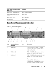
... 1 2 3 4 5 6 15 14 13 12 11 Item Indicator, Button, or Icon Connector 1 PCIe slot 1 2 PCIe slot 2 3 PCIe slot 3 10 987 Description PCI Express (Generation 2) x4-link expansion slot (full-height, 30.99-cm [12.2-in] length) PCIe x4-link Gen 2 expansion slot (lowprofile, 24.13-cm [9.5-in] length) PCIe x8-link Gen 2 expansion slot (fullheight, 24.13-cm [9.5-in] length) or optional...
... 1 2 3 4 5 6 15 14 13 12 11 Item Indicator, Button, or Icon Connector 1 PCIe slot 1 2 PCIe slot 2 3 PCIe slot 3 10 987 Description PCI Express (Generation 2) x4-link expansion slot (full-height, 30.99-cm [12.2-in] length) PCIe x4-link Gen 2 expansion slot (lowprofile, 24.13-cm [9.5-in] length) PCIe x8-link Gen 2 expansion slot (fullheight, 24.13-cm [9.5-in] length) or optional...
Hardware Manual
Page 20
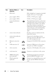
... indicator connector 10 Ethernet connectors (4) 11 USB connectors (2) 12 video connector 13 serial connector 14 iDRAC6 Enterprise port (optional) 15 VFlash media slot (optional) Description PCIe x8-link Gen 2 expansion slot (fullheight, 24.13-cm [9.5-in] length) 870-W or 570-W power supply 870-W or 570-W power supply The identification buttons on a cable management...
... indicator connector 10 Ethernet connectors (4) 11 USB connectors (2) 12 video connector 13 serial connector 14 iDRAC6 Enterprise port (optional) 15 VFlash media slot (optional) Description PCIe x8-link Gen 2 expansion slot (fullheight, 24.13-cm [9.5-in] length) 870-W or 570-W power supply 870-W or 570-W power supply The identification buttons on a cable management...
Hardware Manual
Page 29
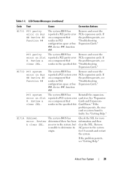
...system BIOS has Remove and reseat the reported a PCI parity error PCIe expansion cards. E1712 PCI system error on Slot #. See "Getting Help." Table 1-1. reported a PCI system error card riser. resides in the specified slot. E1714 Unknown error. Check the SEL for 10 seconds and restart... system BIOS has determined there has been an error in PCI configuration space at bus Expansion Cards." ##, device ##, function ##. If on Slot #. Remove AC power to determine its origin. PCI system error on a component that resides in the system, but is faulty. LCD Status...
...system BIOS has Remove and reseat the reported a PCI parity error PCIe expansion cards. E1712 PCI system error on Slot #. See "Getting Help." Table 1-1. reported a PCI system error card riser. resides in the specified slot. E1714 Unknown error. Check the SEL for 10 seconds and restart... system BIOS has determined there has been an error in PCI configuration space at bus Expansion Cards." ##, device ##, function ##. If on Slot #. Remove AC power to determine its origin. PCI system error on a component that resides in the system, but is faulty. LCD Status...
Hardware Manual
Page 31
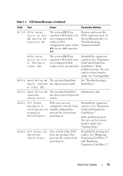
... on a component that resides in the specified slot. Review & clear SEL. reported a PCIe fatal error card riser. E1810 Hard drive ## The specified hard drive fault. removed. Reinstall the expansioncard riser. If the ... 31 If the problem persists, see "Troubleshooting Expansion Cards." See "Expansion on Slot #. Check Riser. resides in PCI configuration space at bus ##, device ##, function ##. E1A12 PCI Riser not detected. Remove and reseat the PCIe expansion cards. has been removed from Reconfigure. powering on a component that Cards ...
... on a component that resides in the specified slot. Review & clear SEL. reported a PCIe fatal error card riser. E1810 Hard drive ## The specified hard drive fault. removed. Reinstall the expansioncard riser. If the ... 31 If the problem persists, see "Troubleshooting Expansion Cards." See "Expansion on Slot #. Check Riser. resides in PCI configuration space at bus ##, device ##, function ##. E1A12 PCI Riser not detected. Remove and reseat the PCIe expansion cards. has been removed from Reconfigure. powering on a component that Cards ...
Hardware Manual
Page 42
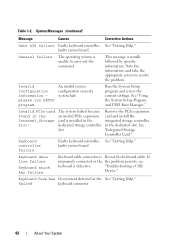
...See "Getting Help." An invalid system configuration caused a system halt. See "Getting Help." Remove the PCIe expansion card and install the integrated storage controller in the Internal_Storage slot! Keyboard controller failure Faulty keyboard controller; Table 1-2. General failure The operating system is Reseat the keyboard... information please run SETUP program. Run the System Setup program and review the current settings. Invalid PCIe card found in the dedicated slot. The system halted because an invalid PCIe expansion card is installed in the dedicated storage controller...
...See "Getting Help." An invalid system configuration caused a system halt. See "Getting Help." Remove the PCIe expansion card and install the integrated storage controller in the Internal_Storage slot! Keyboard controller failure Faulty keyboard controller; Table 1-2. General failure The operating system is Reseat the keyboard... information please run SETUP program. Run the System Setup program and review the current settings. Invalid PCIe card found in the dedicated slot. The system halted because an invalid PCIe expansion card is installed in the dedicated storage controller...
Hardware Manual
Page 45
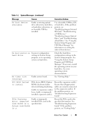
...the System Setup Program and UEFI Boot Manager." If necessary, install the operating system on hard drive. PCIe Training Faulty or improperly Error: Expected installed PCIe card in the specified slot number. See "Troubleshooting Expansion Cards." Use a bootable USB key, CD, or hard drive. Check ...Cards." About Your System 45 No boot sector on setting the order of boot devices. See your hard drive. Cables to install PCIe device BIOS (Option ROM) checksum failure detected during shadowing. Ensure that all appropriate cables are securely connected to the expansion card(s)....
...the System Setup Program and UEFI Boot Manager." If necessary, install the operating system on hard drive. PCIe Training Faulty or improperly Error: Expected installed PCIe card in the specified slot number. See "Troubleshooting Expansion Cards." Use a bootable USB key, CD, or hard drive. Check ...Cards." About Your System 45 No boot sector on setting the order of boot devices. See your hard drive. Cables to install PCIe device BIOS (Option ROM) checksum failure detected during shadowing. Ensure that all appropriate cables are securely connected to the expansion card(s)....
Hardware Manual
Page 76
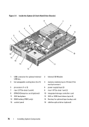
... 1 7 8 9 16 15 14 13 12 10 11 1 USB connector for optional internal USB key 3 hot-swappable cooling fans (4 or 5) 5 processors (1 or 2) 7 riser 2 (PCIe slots 3 and 4) 9 iDRAC6 Enterprise card (optional) 11 SAS backplane 13 RAID battery (PERC only) 15 control panel 2 Internal SD Module 4 memory modules (up to 18 total..., 9 for each processor) 6 power supply bays (2) 8 riser 1 (PCIe slots 1 and 2) 10 integrated storage controller card 12 SAS or SATA hard drives (up to 8) 14 flex bay for optional tape backup unit 16 slimline...
... 1 7 8 9 16 15 14 13 12 10 11 1 USB connector for optional internal USB key 3 hot-swappable cooling fans (4 or 5) 5 processors (1 or 2) 7 riser 2 (PCIe slots 3 and 4) 9 iDRAC6 Enterprise card (optional) 11 SAS backplane 13 RAID battery (PERC only) 15 control panel 2 Internal SD Module 4 memory modules (up to 18 total..., 9 for each processor) 6 power supply bays (2) 8 riser 1 (PCIe slots 1 and 2) 10 integrated storage controller card 12 SAS or SATA hard drives (up to 8) 14 flex bay for optional tape backup unit 16 slimline...
Hardware Manual
Page 119
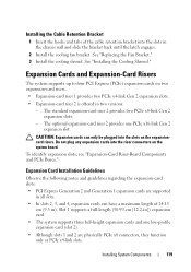
...Card Installation Guidelines Observe the following notes and guidelines regarding the expansion-card slots: • PCI Express Generation 2 and Generation 1 expansion cards are physically PCIe x8 connectors, they function only as PCIe x4-link slots. See "Installing the Cooling Shroud." The optional expansion-card riser 2 ... cm (9.5 in two versions: - Expansion Cards and Expansion-Card Risers The system supports up to four PCI Express (PCIe) expansion cards on the system board. Slot 1 supports a full-length (30.99-cm [12.2-in the chassis wall and slide the bracket back until the ...
...Card Installation Guidelines Observe the following notes and guidelines regarding the expansion-card slots: • PCI Express Generation 2 and Generation 1 expansion cards are physically PCIe x8 connectors, they function only as PCIe x4-link slots. See "Installing the Cooling Shroud." The optional expansion-card riser 2 ... cm (9.5 in two versions: - Expansion Cards and Expansion-Card Risers The system supports up to four PCI Express (PCIe) expansion cards on the system board. Slot 1 supports a full-length (30.99-cm [12.2-in the chassis wall and slide the bracket back until the ...

Hardware Manual
Page 121
...seated in case you need to maintain FCC certification of the system. See Figure 3-26. Filler brackets must be installed over empty expansion-card slots to remove the expansion card. c Insert the card-edge connector firmly into risers 1 and 2 is fully seated. See the documentation that... documentation accompanying the card. 2 Turn off the system, including any expansion-card cables for installing expansion cards into the PCIe card connector until the card is the same except that slots 3 and 4 on riser 2 have card-edge guides for installing 24.13-cm (9.5-in ), align its cable connections...
...seated in case you need to maintain FCC certification of the system. See Figure 3-26. Filler brackets must be installed over empty expansion-card slots to remove the expansion card. c Insert the card-edge connector firmly into risers 1 and 2 is fully seated. See the documentation that... documentation accompanying the card. 2 Turn off the system, including any expansion-card cables for installing expansion cards into the PCIe card connector until the card is the same except that slots 3 and 4 on riser 2 have card-edge guides for installing 24.13-cm (9.5-in ), align its cable connections...

Hardware Manual
Page 185
x4 link (low profile, 24.13- cm [12.2-in] length) cm [9.5-in] length) 3 storage controller socket 4 card edge connector 5 release button Jumpers and Connectors 185 Expansion-Card Riser-Board Components and PCIe Buses Figure 6-6. x4 link (full-height, 30.99- 2 slot 2 PCIe - PCIe Expansion-Card Riser 1 Components 1 2 5 4 3 1 slot 1 PCIe -
x4 link (low profile, 24.13- cm [12.2-in] length) cm [9.5-in] length) 3 storage controller socket 4 card edge connector 5 release button Jumpers and Connectors 185 Expansion-Card Riser-Board Components and PCIe Buses Figure 6-6. x4 link (full-height, 30.99- 2 slot 2 PCIe - PCIe Expansion-Card Riser 1 Components 1 2 5 4 3 1 slot 1 PCIe -

Hardware Manual
Page 186
cm [9.5-in ] length) 5 pin collars (2) 2 screw 4 slot 4 PCIe x8 link (full-height, 24.13- Standard PCIe Expansion-Card Riser 2 Components 1 2 3 4 5 6 1 chassis intrusion switch 3 slot 3 PCIe x8 link (full-height, 24.13- Figure 6-7. cm [9.5-in ] length) 6 card edge connector 186 Jumpers and Connectors
cm [9.5-in ] length) 5 pin collars (2) 2 screw 4 slot 4 PCIe x8 link (full-height, 24.13- Standard PCIe Expansion-Card Riser 2 Components 1 2 3 4 5 6 1 chassis intrusion switch 3 slot 3 PCIe x8 link (full-height, 24.13- Figure 6-7. cm [9.5-in ] length) 6 card edge connector 186 Jumpers and Connectors

Hardware Manual
Page 187
You should only perform troubleshooting and simple repairs as authorized in your warranty. Optional PCIe x16 Expansion-Card Riser 2 Components 1 2 3 4 5 1 chassis intrusion switch 2 plunger 3 slot 3 PCIe x16 link (full-height, 24.13- 4 pin collars (2) cm [9.5-in] length) 5 card edge connector Disabling a ... the system from the electrical outlet. 2 Open the system. Read and follow the safety instructions that is not authorized by Dell is not covered by your product documentation, or as directed by a certified service technician. Jumpers and Connectors 187 See "Opening...
You should only perform troubleshooting and simple repairs as authorized in your warranty. Optional PCIe x16 Expansion-Card Riser 2 Components 1 2 3 4 5 1 chassis intrusion switch 2 plunger 3 slot 3 PCIe x16 link (full-height, 24.13- 4 pin collars (2) cm [9.5-in] length) 5 card edge connector Disabling a ... the system from the electrical outlet. 2 Open the system. Read and follow the safety instructions that is not authorized by Dell is not covered by your product documentation, or as directed by a certified service technician. Jumpers and Connectors 187 See "Opening...
Technical Guide
Page 9
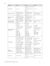
... Enterprise, vFlash iDRAC6 Express, BMC, IPMI 2.0, Dell OpenManage™ Optional: iDRAC6 Enterprise, vFlash 2 PCIe x8 G2 2 PCIe x8 + 2 PCIe x4 G2 or 1 x PCIe x16 + 2 PCIe x4 G2 5 PCIe x8 + 2 PCIe x4 PowerEdge R710 Technical Guide 9 Dell Feature Drive Bays Hard Drive Types External Drive Bay(s) Embedded Hard Drive Controller Optional Storage Controller Availability Server Management I/O Slots R610 R710 R810 6 x 2.5‖ 4 x 3.5" with optional flex...
... Enterprise, vFlash iDRAC6 Express, BMC, IPMI 2.0, Dell OpenManage™ Optional: iDRAC6 Enterprise, vFlash 2 PCIe x8 G2 2 PCIe x8 + 2 PCIe x4 G2 or 1 x PCIe x16 + 2 PCIe x4 G2 5 PCIe x8 + 2 PCIe x4 PowerEdge R710 Technical Guide 9 Dell Feature Drive Bays Hard Drive Types External Drive Bay(s) Embedded Hard Drive Controller Optional Storage Controller Availability Server Management I/O Slots R610 R710 R810 6 x 2.5‖ 4 x 3.5" with optional flex...
Technical Guide
Page 12
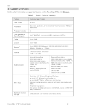
...174; QuickPath Interconnect (QPI) (maximum 6.4GT/s) Cache Chipset Up to 12MB Intel® 5520 Memory1 Up to 288GB (18 DIMM slots): 1GB/2GB/4GB/8GB/16GB DDR3 800MHz, 1066MHz, or 1333MHz I/O Slots 2 PCIe x8 + 2 PCIe x4 Gen2 or 1 x16 + 2 x4 Gen2 RAID Controller Internal Controllers: PERC H200 (6Gb/s) PERC H700 (6Gb/s) (nonvolatile ... choice of DVD-ROM, Combo CD-RW/DVDROM, or DVD+RW Maximum Internal Storage 12TB (with 2TB 3.5‖ nearline SAS or SATA drives) PowerEdge R710 Technical Guide 12 Table 2. Dell 3 System Overview For the latest information on supported features for the...
...174; QuickPath Interconnect (QPI) (maximum 6.4GT/s) Cache Chipset Up to 12MB Intel® 5520 Memory1 Up to 288GB (18 DIMM slots): 1GB/2GB/4GB/8GB/16GB DDR3 800MHz, 1066MHz, or 1333MHz I/O Slots 2 PCIe x8 + 2 PCIe x4 Gen2 or 1 x16 + 2 x4 Gen2 RAID Controller Internal Controllers: PERC H200 (6Gb/s) PERC H700 (6Gb/s) (nonvolatile ... choice of DVD-ROM, Combo CD-RW/DVDROM, or DVD+RW Maximum Internal Storage 12TB (with 2TB 3.5‖ nearline SAS or SATA drives) PowerEdge R710 Technical Guide 12 Table 2. Dell 3 System Overview For the latest information on supported features for the...
Technical Guide
Page 39
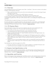
... the PERC 6i or SAS 6/iR. The default Riser 2 consists of the Dell PowerEdge R710 Systems Hardware Owner's Manual on Support.dell.com. The slots meet the following riser restrictions apply for the R710: The riser connectors on the planar do not support plugging in a standard PCI... Express card. Two R710 risers must be installed or the system will not power up. 11.3 Express Card Specifications (x16) For information about x16 PCIe card specifications, see the Expansion Cards and Expansion-Card Risers section in Slot 1 on Riser 1 System support ...
... the PERC 6i or SAS 6/iR. The default Riser 2 consists of the Dell PowerEdge R710 Systems Hardware Owner's Manual on Support.dell.com. The slots meet the following riser restrictions apply for the R710: The riser connectors on the planar do not support plugging in a standard PCI... Express card. Two R710 risers must be installed or the system will not power up. 11.3 Express Card Specifications (x16) For information about x16 PCIe card specifications, see the Expansion Cards and Expansion-Card Risers section in Slot 1 on Riser 1 System support ...
Technical Guide
Page 40
PowerEdge R710 Technical Guide 40 Dell 11.5 PCI Card Dimensions For information about PCIe slots and card dimensions, see the Expansion Cards and Expansion-Card Risers section in the Installing System Components chapter in the Dell PowerEdge R710 Systems Hardware Owner's Manual on Support.Dell.com.
PowerEdge R710 Technical Guide 40 Dell 11.5 PCI Card Dimensions For information about PCIe slots and card dimensions, see the Expansion Cards and Expansion-Card Risers section in the Installing System Components chapter in the Dell PowerEdge R710 Systems Hardware Owner's Manual on Support.Dell.com.
Technical Guide
Page 45
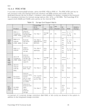
...Table 12. It supports the internal 6 Gb/s backplane interface for backup. The PERC H700 card has its own processor with a PCI Express Gen2 host interface and DDR2 memory and installs into the dedicated internal SAS slot on the internal H700. Storage Card Support... or external SCSI tape/ legacy Yes-Max 2 PCIe slot external storage N/A N/A x8 Yes x1 int N/A N/A SCSI int N/A N/A SCSI ext A maximum of 2 external storage controllers (Dell PERC or SAS cards) are allowed in the system in addition to the integrated storage controller. PowerEdge R710 Technical Guide 45
...Table 12. It supports the internal 6 Gb/s backplane interface for backup. The PERC H700 card has its own processor with a PCI Express Gen2 host interface and DDR2 memory and installs into the dedicated internal SAS slot on the internal H700. Storage Card Support... or external SCSI tape/ legacy Yes-Max 2 PCIe slot external storage N/A N/A x8 Yes x1 int N/A N/A SCSI int N/A N/A SCSI ext A maximum of 2 external storage controllers (Dell PERC or SAS cards) are allowed in the system in addition to the integrated storage controller. PowerEdge R710 Technical Guide 45


