Setup and Features Information Tech Sheet
Page 2
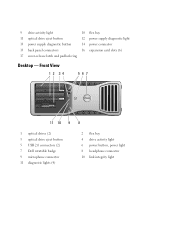
Front View 1 2 34 567 11 10 9 8 1 optical drives (2) 3 optical drive eject button 5 USB 2.0 connectors (2) 7 Dell rotatable badge 9 microphone connector 11 diagnostic lights (4) 2 flex bay 4 drive activity light 6 power button, power light 8 headphone connector 10 link integrity light 9 drive activity light 10 flex bay 11 optical drive eject button 12 power supply diagnostic light 13 power supply diagnostic button 14 power connector 15 back panel connectors 16 expansion card slots (6) 17 cover-release latch and padlock ring Desktop -
Front View 1 2 34 567 11 10 9 8 1 optical drives (2) 3 optical drive eject button 5 USB 2.0 connectors (2) 7 Dell rotatable badge 9 microphone connector 11 diagnostic lights (4) 2 flex bay 4 drive activity light 6 power button, power light 8 headphone connector 10 link integrity light 9 drive activity light 10 flex bay 11 optical drive eject button 12 power supply diagnostic light 13 power supply diagnostic button 14 power connector 15 back panel connectors 16 expansion card slots (6) 17 cover-release latch and padlock ring Desktop -
Setup and Features Information Tech Sheet
Page 3
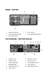
Desktop - Back Panel Connectors 1 2 34 5 67 11 1 parallel connector 3 eSATA connector 5 network activity light 7 link integrity light 9 USB 2.0 connectors (6) 11 serial connector 8 10 9 2 PS/2 mouse connector 4 line-out connector 6 network adapter connector 8 line-in connector 10 PS/2 keyboard connector Back View 1 2 3 4 5 1 expansion card slots (6) 3 power supply diagnostic light 5 back panel connectors 2 power connector 4 power supply diagnostic button Tower and Desktop -
Desktop - Back Panel Connectors 1 2 34 5 67 11 1 parallel connector 3 eSATA connector 5 network activity light 7 link integrity light 9 USB 2.0 connectors (6) 11 serial connector 8 10 9 2 PS/2 mouse connector 4 line-out connector 6 network adapter connector 8 line-in connector 10 PS/2 keyboard connector Back View 1 2 3 4 5 1 expansion card slots (6) 3 power supply diagnostic light 5 back panel connectors 2 power connector 4 power supply diagnostic button Tower and Desktop -

Setup and Features Information Tech Sheet
Page 7
... (no light - indicates that the power supply is in sleep state; System is good - Video Type: Discrete Drives Externally accessible Internally accessible Available devices Controls and Lights Front of the computer: Power button Power light Drive activity light Link integrity light PCI Express 2.0 x16 (two slots) NOTE: Support for power-on state amber light - in...
... (no light - indicates that the power supply is in sleep state; System is good - Video Type: Discrete Drives Externally accessible Internally accessible Available devices Controls and Lights Front of the computer: Power button Power light Drive activity light Link integrity light PCI Express 2.0 x16 (two slots) NOTE: Support for power-on state amber light - in...
Setup and Features Information Tech Sheet
Page 8
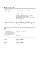
... green light - A good connection at 100Mbs exists between the network and the computer yellow light - The computer is available for the power supply Power AC power supply: Voltage (see the safety information that no power is not detecting a physical connection to the network Network activity light (on integrated network adapter) green light - A good connection at 1000Mbs... cm (18.40 inches) 17.20 kg (38 lbs) A good connection at 10Mbs exists between the network and the computer off (no light) - Indicates the power supply is working properly off (no light) -
... green light - A good connection at 100Mbs exists between the network and the computer yellow light - The computer is available for the power supply Power AC power supply: Voltage (see the safety information that no power is not detecting a physical connection to the network Network activity light (on integrated network adapter) green light - A good connection at 1000Mbs... cm (18.40 inches) 17.20 kg (38 lbs) A good connection at 10Mbs exists between the network and the computer off (no light) - Indicates the power supply is working properly off (no light) -
Service Manual
Page 2
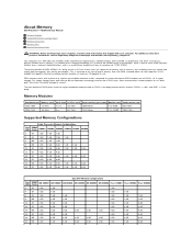
... higher latency. About Memory Dell Precision™ T5500 Service Manual Memory Modules Supported Memory Configurations Memory Subsystem Memory Slots Memory Population Rules WARNING: Before working inside your computer, read the safety information that shipped with a promise of a power consumption reduction of 30% compared to current commercial DDR2 modules due to DDR3's 1.5 V supply voltage. DDR3 SDRAM...
... higher latency. About Memory Dell Precision™ T5500 Service Manual Memory Modules Supported Memory Configurations Memory Subsystem Memory Slots Memory Population Rules WARNING: Before working inside your computer, read the safety information that shipped with a promise of a power consumption reduction of 30% compared to current commercial DDR2 modules due to DDR3's 1.5 V supply voltage. DDR3 SDRAM...
Service Manual
Page 10
... of the light at the diagnostic lights for all four lights to be replaced. To exit the Dell Diagnostics and restart the computer, close the Main Menu screen. Indicates system has power, but either S1 or S3. If the Hard Drive light on your computer. Diagnostic Light Codes...or Soft off , light is on the front control panel to indicate it is probable that the power supply is probable that the power supply needs to your hardware configuration for running the Dell Diagnostics from system setup, memory, and various internal tests, and it displays the information in the ...
... of the light at the diagnostic lights for all four lights to be replaced. To exit the Dell Diagnostics and restart the computer, close the Main Menu screen. Indicates system has power, but either S1 or S3. If the Hard Drive light on your computer. Diagnostic Light Codes...or Soft off , light is on the front control panel to indicate it is probable that the power supply is probable that the power supply needs to your hardware configuration for running the Dell Diagnostics from system setup, memory, and various internal tests, and it displays the information in the ...
Service Manual
Page 11
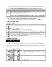
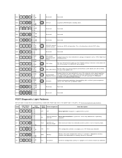
...POST Diagnostic Light Patterns All POST codes except S0 are accompanied by a plug-in one of the onboard system board regulators. Off OFF OFF Power light Off. Off 2- Off 3- Off 4- Off 3- Solid 4- Off 3- Solid 1- Off 2- Off 3- Green 4- This is operating...3- to POST states. Off 3- Off 1- Off 2- Off 4- Green 2- Off 2- Off 2- Solid 4- BIOS not execution. If the power light is supplied to RAM Windows Standby State. Off 2- Off 2- Appropriate memory modules were detected but a memory failure has occurred. 1- Pb2 Pb3 Pb4 Pb5 ...
...POST Diagnostic Light Patterns All POST codes except S0 are accompanied by a plug-in one of the onboard system board regulators. Off OFF OFF Power light Off. Off 2- Off 3- Off 4- Off 3- Solid 4- Off 3- Solid 1- Off 2- Off 3- Green 4- This is operating...3- to POST states. Off 3- Off 1- Off 2- Off 4- Green 2- Off 2- Off 2- Solid 4- BIOS not execution. If the power light is supplied to RAM Windows Standby State. Off 2- Off 2- Appropriate memory modules were detected but a memory failure has occurred. 1- Pb2 Pb3 Pb4 Pb5 ...
Service Manual
Page 14
Adding and Replacing Parts Dell Precision™ T5500 Service Manual Cover Battery Drives Bezel Hard Drive Tray Front Fan Assembly Memory Card Reader Memory Dual Processor Riser (Optional) System Board I/O Data Cable Chassis Intrusion Switch Front Bezel Hard Drive Floppy Drive Optical Drive Expansion Cards Heat Sink and Processor Power Supply
Adding and Replacing Parts Dell Precision™ T5500 Service Manual Cover Battery Drives Bezel Hard Drive Tray Front Fan Assembly Memory Card Reader Memory Dual Processor Riser (Optional) System Board I/O Data Cable Chassis Intrusion Switch Front Bezel Hard Drive Floppy Drive Optical Drive Expansion Cards Heat Sink and Processor Power Supply
Service Manual
Page 17
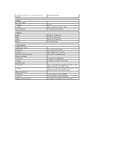
Network activity light (on integrated network adapter) Power DC power supply: Wattage Voltage Coin-cell battery Physical Height Width Depth Weight Environmental Temperature range: Operating Storage Relative humidity (maximum): Maximum vibration: Operating Storage Maximum shock: Operating ...
Network activity light (on integrated network adapter) Power DC power supply: Wattage Voltage Coin-cell battery Physical Height Width Depth Weight Environmental Temperature range: Operating Storage Relative humidity (maximum): Maximum vibration: Operating Storage Maximum shock: Operating ...
Service Manual
Page 65
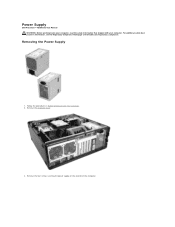
For additional safety best practices information, see the Regulatory Compliance Homepage at www.dell.com/regulatory_compliance. Power Supply Dell Precision™ T5500 Service Manual WARNING: Before working inside your computer, read the safety information that shipped with your computer. Remove the computer cover. 3. Removing the Power Supply 1. Follow the procedures in Before Working Inside Your Computer. 2. Remove the four screws securing the power supply on the outside of the computer.
For additional safety best practices information, see the Regulatory Compliance Homepage at www.dell.com/regulatory_compliance. Power Supply Dell Precision™ T5500 Service Manual WARNING: Before working inside your computer, read the safety information that shipped with your computer. Remove the computer cover. 3. Removing the Power Supply 1. Follow the procedures in Before Working Inside Your Computer. 2. Remove the four screws securing the power supply on the outside of the computer.

Service Manual
Page 66
Rotate the expansion card retention arm toward the outside of the computer. 5. Disconnect the power supply cable from the power supply. 4.
Rotate the expansion card retention arm toward the outside of the computer. 5. Disconnect the power supply cable from the power supply. 4.

Service Manual
Page 67
Push down and hold the power supply release clip (1), then slide the power supply toward the center of the computer (2). 7. 6. Remove the power supply from the system at an angle.
Push down and hold the power supply release clip (1), then slide the power supply toward the center of the computer (2). 7. 6. Remove the power supply from the system at an angle.

Service Manual
Page 71
Disconnect the power supply cable from the system board. 13. 12. Disconnect the hard drive and optical drive data cables from the system board.
Disconnect the power supply cable from the system board. 13. 12. Disconnect the hard drive and optical drive data cables from the system board.

Service Manual
Page 72
14. Remove the three screws that secure the dual processor riser to the system board. Disconnect the power supply data cable from the system board. 15.
14. Remove the three screws that secure the dual processor riser to the system board. Disconnect the power supply data cable from the system board. 15.


