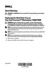
Replacing the Hard-Drive Tray
Page 1
... Compliance Homepage at support.dell.com/manuals. 1 Turn off your computer. 2 Disconnect all the external cables from the hard-drive tray, if the hard-drive tray obstructs the cables on Your Dell Precision™ Workstation T3500/T5500 WARNING: Before working inside your computer, read the safety information that shipped with your computer. NOTE: For more information on removing and replacing parts on the Dell Support website at www.dell.com/regulatory_compliance. About...
... Compliance Homepage at support.dell.com/manuals. 1 Turn off your computer. 2 Disconnect all the external cables from the hard-drive tray, if the hard-drive tray obstructs the cables on Your Dell Precision™ Workstation T3500/T5500 WARNING: Before working inside your computer, read the safety information that shipped with your computer. NOTE: For more information on removing and replacing parts on the Dell Support website at www.dell.com/regulatory_compliance. About...
Replacing the Hard-Drive Tray
Page 4
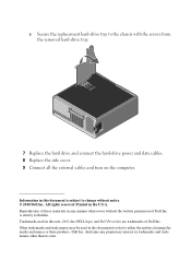
...other than its own. Other trademarks and trade names may be used in this text: Dell, the DELL logo, and Dell Precision are trademarks of Dell Inc. c Secure the replacement hard-drive tray to either the entities claiming the marks and names or...change without the written permission of Dell Inc. Dell Inc. Trademarks used in the U.S.A. Printed in this document to refer to the chassis with the screws from the removed hard-drive tray. 7 Replace the hard drive and connect the hard-drive power and data cables. 8 Replace the side cover. 9 Connect all the external cables and turn...
...other than its own. Other trademarks and trade names may be used in this text: Dell, the DELL logo, and Dell Precision are trademarks of Dell Inc. c Secure the replacement hard-drive tray to either the entities claiming the marks and names or...change without the written permission of Dell Inc. Dell Inc. Trademarks used in the U.S.A. Printed in this document to refer to the chassis with the screws from the removed hard-drive tray. 7 Replace the hard drive and connect the hard-drive power and data cables. 8 Replace the side cover. 9 Connect all the external cables and turn...
Setup and Features Information Tech Sheet
Page 3
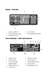
Back Panel Connectors 1 2 34 5 67 11 1 parallel connector 3 eSATA connector 5 network activity light 7 link integrity light 9 USB 2.0 connectors (6) 11 serial connector 8 10 9 2 PS/2 mouse connector 4 line-out connector 6 network adapter connector 8 line-in connector 10 PS/2 keyboard connector Back View 1 2 3 4 5 1 expansion card slots (6) 3 power supply diagnostic light 5 back panel connectors 2 power connector 4 power supply diagnostic button Tower and Desktop - Desktop -
Back Panel Connectors 1 2 34 5 67 11 1 parallel connector 3 eSATA connector 5 network activity light 7 link integrity light 9 USB 2.0 connectors (6) 11 serial connector 8 10 9 2 PS/2 mouse connector 4 line-out connector 6 network adapter connector 8 line-in connector 10 PS/2 keyboard connector Back View 1 2 3 4 5 1 expansion card slots (6) 3 power supply diagnostic light 5 back panel connectors 2 power connector 4 power supply diagnostic button Tower and Desktop - Desktop -
Setup and Features Information Tech Sheet
Page 5
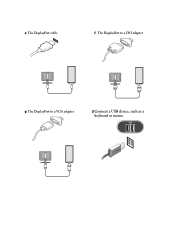
e The DisplayPort cable f The DisplayPort to a DVI adapter g The DisplayPort to a VGA adapter 2 Connect a USB device, such as a keyboard or mouse.
e The DisplayPort cable f The DisplayPort to a DVI adapter g The DisplayPort to a VGA adapter 2 Connect a USB device, such as a keyboard or mouse.

Setup and Features Information Tech Sheet
Page 6
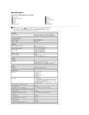
For a complete and current listing of the specifications for your computer. Processor Type: System Information System chipset Data bus width Dual-Core Intel® Xeon® Processor 5500 series Quad-Core Intel® Xeon® Processor 5500 series Intel 5500/5520 64 bits Specifications NOTE: The following specifications are only those required by law to ship with your computer, go to support.dell.com. 3 Connect the network cable. 4 Connect the modem (if installed). 5 Connect the power cable(s). 6 Press the power buttons on the monitor and the computer.
For a complete and current listing of the specifications for your computer. Processor Type: System Information System chipset Data bus width Dual-Core Intel® Xeon® Processor 5500 series Quad-Core Intel® Xeon® Processor 5500 series Intel 5500/5520 64 bits Specifications NOTE: The following specifications are only those required by law to ship with your computer, go to support.dell.com. 3 Connect the network cable. 4 Connect the modem (if installed). 5 Connect the power cable(s). 6 Press the power buttons on the monitor and the computer.

Setup and Features Information Tech Sheet
Page 7
... the SATA hard drive or CD/DVD green light - The blinking amber light indicates a problem with an optional adapter) NOTE: Supports a maximum of three hard drives push button green light - A solid amber light indicates that the system board cannot start initialization but that the computer is in normal operating state no light) - Video Type: Discrete Drives Externally accessible Internally accessible Available devices Controls and Lights Front of the computer: Power button Power light Drive activity light Link integrity light PCI Express 2.0 x16 (two slots) NOTE: Support for power-on...
... the SATA hard drive or CD/DVD green light - The blinking amber light indicates a problem with an optional adapter) NOTE: Supports a maximum of three hard drives push button green light - A solid amber light indicates that the system board cannot start initialization but that the computer is in normal operating state no light) - Video Type: Discrete Drives Externally accessible Internally accessible Available devices Controls and Lights Front of the computer: Power button Power light Drive activity light Link integrity light PCI Express 2.0 x16 (two slots) NOTE: Support for power-on...
Service Manual
Page 1
... the Windows Vista start button are either the entities claiming the marks and names or their products. Dell Inc. Dell Precision™ T5500 Service Manual Working on Your Computer Adding and Replacing Parts Specifications Diagnostics About Memory About Your System Board System Setup Notes, Cautions, and Warnings NOTE: A NOTE indicates important information that helps you purchased a Dell™ n Series computer, any references in this document to Microsoft® Windows® operating systems are...
... the Windows Vista start button are either the entities claiming the marks and names or their products. Dell Inc. Dell Precision™ T5500 Service Manual Working on Your Computer Adding and Replacing Parts Specifications Diagnostics About Memory About Your System Board System Setup Notes, Cautions, and Warnings NOTE: A NOTE indicates important information that helps you purchased a Dell™ n Series computer, any references in this document to Microsoft® Windows® operating systems are...
Service Manual
Page 2
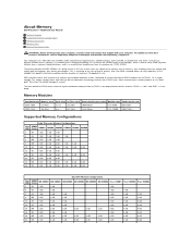
... use "dualgate" transistors to 8 gigabit, effectively enabling memory modules of DDR3 comes from the higher bandwidth made possible by DDR3's 8 bit deep prefetch buffer, whereas DDR2's is 4 bits, and DDR's is 2 bits deep. Your computer uses 1066 MHz and 1333Mhz DDR3 unbuffered or registered ECC SDRAM memory. About Memory Dell Precision™ T5500 Service Manual Memory Modules Supported Memory Configurations Memory Subsystem Memory Slots Memory Population Rules WARNING: Before working inside...
... use "dualgate" transistors to 8 gigabit, effectively enabling memory modules of DDR3 comes from the higher bandwidth made possible by DDR3's 8 bit deep prefetch buffer, whereas DDR2's is 4 bits, and DDR's is 2 bits deep. Your computer uses 1066 MHz and 1333Mhz DDR3 unbuffered or registered ECC SDRAM memory. About Memory Dell Precision™ T5500 Service Manual Memory Modules Supported Memory Configurations Memory Subsystem Memory Slots Memory Population Rules WARNING: Before working inside...
Service Manual
Page 5
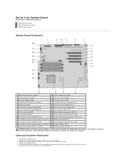
... 4 and set the jumper plug aside. 4. Connect your keyboard and mouse, then connect your computer. Remove the computer cover. 2. Locate the 4-pin password connector (PSWD) on . 6. About Your System Board Dell Precision™ T5500 Service Manual System Board Schematic Clearing Forgotten Passwords Clearing CMOS Settings System Board Schematic 1 Main Power Connector (POWER1) 15 Type A USB Port (INT_USB2) 2 SATA Connectors (SATA0-4) 16 CPU Riser 2 (CPU2_RSR2) 3 Password Jumper (PSWD) 17 CPU Riser 1 (CPU_RSR1) 4 Hard Drive Fan Connector (FAN_HDD) 18 >Primary Processor Connector (CPU1...
... 4 and set the jumper plug aside. 4. Connect your keyboard and mouse, then connect your computer. Remove the computer cover. 2. Locate the 4-pin password connector (PSWD) on . 6. About Your System Board Dell Precision™ T5500 Service Manual System Board Schematic Clearing Forgotten Passwords Clearing CMOS Settings System Board Schematic 1 Main Power Connector (POWER1) 15 Type A USB Port (INT_USB2) 2 SATA Connectors (SATA0-4) 16 CPU Riser 2 (CPU2_RSR2) 3 Password Jumper (PSWD) 17 CPU Riser 1 (CPU_RSR1) 4 Hard Drive Fan Connector (FAN_HDD) 18 >Primary Processor Connector (CPU1...

Service Manual
Page 6
... computer using the operating system, press and hold the power button for the CMOS to clear. 7. NOTE: The password jumper plug must be reinstalled on . Connect your computer and devices to electrical outlets, and then turn them on the password jumper pins in AC power to clear the CMOS setting. 1. Remove the computer cover. 2. Replace the computer cover. 9. Connect your computer and devices to pins 3 and 4 of the CMOS jumper. 6. Disconnect the keyboard and mouse, then disconnect the computer and monitor...
... computer using the operating system, press and hold the power button for the CMOS to clear. 7. NOTE: The password jumper plug must be reinstalled on . Connect your computer and devices to electrical outlets, and then turn them on the password jumper pins in AC power to clear the CMOS setting. 1. Remove the computer cover. 2. Replace the computer cover. 9. Connect your computer and devices to pins 3 and 4 of the CMOS jumper. 6. Disconnect the keyboard and mouse, then disconnect the computer and monitor...
Service Manual
Page 7
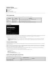
... be used to call up ) configuration l Basic device configuration settings l System security and hard drive password settings System Setup Navigation Keystrokes Use the following keystrokes to view and/or change any settings. System setup key functions are listed at the Dell™ Logo screen. Entering System Setup Press to a specific device (e.g., floppy, CD-ROM, or hard drive). You can change settings that you cannot change the user-definable settings. One-time boot and diagnostics utility menu Bypass the BIOS boot sequence and boot directly to the network Boot Menu As...
... be used to call up ) configuration l Basic device configuration settings l System security and hard drive password settings System Setup Navigation Keystrokes Use the following keystrokes to view and/or change any settings. System setup key functions are listed at the Dell™ Logo screen. Entering System Setup Press to a specific device (e.g., floppy, CD-ROM, or hard drive). You can change settings that you cannot change the user-definable settings. One-time boot and diagnostics utility menu Bypass the BIOS boot sequence and boot directly to the network Boot Menu As...
Service Manual
Page 9
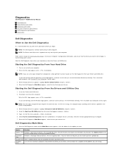
... Drivers and Utilities disc. Start the Dell Diagnostics from either your hard drive or from the numbered list. When the boot device list appears, highlight Boot to select a test based on (or restart) your computer. Select Run the 32 Bit Dell Diagnostics from the Drivers and Utilities disc. Turn on the symptom of tracing the problem quickly. NOTE: The next steps change the boot sequence for the option you see the Microsoft® Windows® desktop. Dell Diagnostics Main Menu 1. Enter system setup...
... Drivers and Utilities disc. Start the Dell Diagnostics from either your hard drive or from the numbered list. When the boot device list appears, highlight Boot to select a test based on (or restart) your computer. Select Run the 32 Bit Dell Diagnostics from the Drivers and Utilities disc. Turn on the symptom of tracing the problem quickly. NOTE: The next steps change the boot sequence for the option you see the Microsoft® Windows® desktop. Dell Diagnostics Main Menu 1. Enter system setup...
Service Manual
Page 10
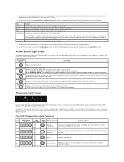
... light at the diagnostic lights for running the Dell Diagnostics from the Drivers and Utilities disc, remove the disc. 5. The device list may indicate requirements for further information. To exit the Dell Diagnostics and restart the computer, close the Main Menu screen. Power Light State Off Power is in . If the Hard Drive light on with no failures detected. Off 3- Off 2- Off 1- ACPI S0; 2. If you go down the error code and problem description and follow the instructions...
... light at the diagnostic lights for running the Dell Diagnostics from the Drivers and Utilities disc, remove the disc. 5. The device list may indicate requirements for further information. To exit the Dell Diagnostics and restart the computer, close the Main Menu screen. Power Light State Off Power is in . If the Hard Drive light on with no failures detected. Off 3- Off 2- Off 1- ACPI S0; 2. If you go down the error code and problem description and follow the instructions...
Service Manual
Page 11
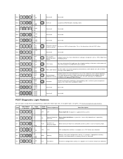
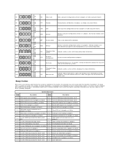
... 4- Appropriate memory modules were detected but a memory failure has occurred. 1- Off 2- Off 1- Off 1- Blink 1- Off 3- Off 4- Off 2- Off PCI PCI device PCI device configuration activity is now in device creating a short on . Solid 4- Off 2- Blink 4- Off 3- Green 2- This could be properly connected to BIOS control Reserved Reserved Non-System board Regulator Failure A power failure has been detected on a plug-in Recovery Mode BIOS checksum failure was detected. 1- Off 2- Off 4- Solid MEM Memory Memory subsystem configuration activity is...
... 4- Appropriate memory modules were detected but a memory failure has occurred. 1- Off 2- Off 1- Off 1- Blink 1- Off 3- Off 4- Off 2- Off PCI PCI device PCI device configuration activity is now in device creating a short on . Solid 4- Off 2- Blink 4- Off 3- Green 2- This could be properly connected to BIOS control Reserved Reserved Non-System board Regulator Failure A power failure has been detected on a plug-in Recovery Mode BIOS checksum failure was detected. 1- Off 2- Off 4- Solid MEM Memory Memory subsystem configuration activity is...
Service Manual
Page 12
... line failure (multi 1-3-3 bit) CMOS power fail and checksum test in 3-3-1 progress 1-3-4 1st 64 K RAM odd/even logic failure 3-3-2 CMOS Config info validation in progress 1-4-1 1st 64 K RAM address line failure 3-3-3 RTC/Keyboard controller not found 1-4-2 1st 64 K RAM parity test in progress or failure 3-3-4 Screen memory test in progress or failure 1-4-3 Fail-safe timer test in progress 3-4-1 Screen initialization test in progress or failure 1-4-4 Software NMI port test in progress 3-4-2 Screen retrace tests test in nonvolatile random-access memory...
... line failure (multi 1-3-3 bit) CMOS power fail and checksum test in 3-3-1 progress 1-3-4 1st 64 K RAM odd/even logic failure 3-3-2 CMOS Config info validation in progress 1-4-1 1st 64 K RAM address line failure 3-3-3 RTC/Keyboard controller not found 1-4-2 1st 64 K RAM parity test in progress or failure 3-3-4 Screen memory test in progress or failure 1-4-3 Fail-safe timer test in progress 3-4-1 Screen initialization test in progress or failure 1-4-4 Software NMI port test in progress 3-4-2 Screen retrace tests test in nonvolatile random-access memory...
Service Manual
Page 14
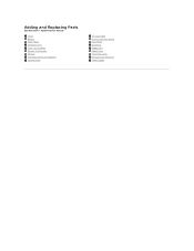
Adding and Replacing Parts Dell Precision™ T5500 Service Manual Cover Battery Drives Bezel Hard Drive Tray Front Fan Assembly Memory Card Reader Memory Dual Processor Riser (Optional) System Board I/O Data Cable Chassis Intrusion Switch Front Bezel Hard Drive Floppy Drive Optical Drive Expansion Cards Heat Sink and Processor Power Supply
Adding and Replacing Parts Dell Precision™ T5500 Service Manual Cover Battery Drives Bezel Hard Drive Tray Front Fan Assembly Memory Card Reader Memory Dual Processor Riser (Optional) System Board I/O Data Cable Chassis Intrusion Switch Front Bezel Hard Drive Floppy Drive Optical Drive Expansion Cards Heat Sink and Processor Power Supply
Service Manual
Page 15
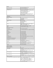
... memory Maximum memory Video Video type: Discrete Audio Audio type Six Nine with optional riser 1 GB, 2 GB, 4 GB, or 8 GB DDR3 1066 MHz SDRAM DDR3 1333 MHz SDRAM (DDR3 800 MHz capable) 1 GB 48 GB 72 GB with optional riser PCI Express 2.0 x16 (two slots) NOTE: Support for two full height, full length graphics cards using the PCIe x16 graphics card slot. Specifications Dell Precision™ T5500/T5500n Service Manual Processors System Information Memory Video Audio Expansion Bus Drives Connectors Controls and Lights Power...
... memory Maximum memory Video Video type: Discrete Audio Audio type Six Nine with optional riser 1 GB, 2 GB, 4 GB, or 8 GB DDR3 1066 MHz SDRAM DDR3 1333 MHz SDRAM (DDR3 800 MHz capable) 1 GB 48 GB 72 GB with optional riser PCI Express 2.0 x16 (two slots) NOTE: Support for two full height, full length graphics cards using the PCIe x16 graphics card slot. Specifications Dell Precision™ T5500/T5500n Service Manual Processors System Information Memory Video Audio Expansion Bus Drives Connectors Controls and Lights Power...
Service Manual
Page 16
...optional adapter) Connectors External connectors: Video Network adapter USB Audio Serial PS/2 System board connectors: Serial ATA Internal USB device Fans: Front fan Card cage fan HDD fan PCI PCI-X PCI Express x8 PCI Express x16 Front panel control (USB included) Front panel audio HDA header Processor Memory Power 12 V Power (Depending on optional riser One 24-pin connector Controls and Lights Front of the computer Power button Power light Drive activity light Link integrity light Back of the following 5.25-inch devices: SATA DVD-ROM/CD-RW Combo, DVD +/- RW Blu-ray™drive, HD/DVD...
...optional adapter) Connectors External connectors: Video Network adapter USB Audio Serial PS/2 System board connectors: Serial ATA Internal USB device Fans: Front fan Card cage fan HDD fan PCI PCI-X PCI Express x8 PCI Express x16 Front panel control (USB included) Front panel audio HDA header Processor Memory Power 12 V Power (Depending on optional riser One 24-pin connector Controls and Lights Front of the computer Power button Power light Drive activity light Link integrity light Back of the following 5.25-inch devices: SATA DVD-ROM/CD-RW Combo, DVD +/- RW Blu-ray™drive, HD/DVD...
Service Manual
Page 79
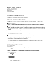
... l Flash BIOS update program CD (see Removing and Replacing the Computer Cover). Hold a card by its edges or by its pull-tab, not on the cable itself. As you pull connectors apart, keep them evenly aligned to ground the system board. 7. While you work surface is unplugged to avoid bending any connector pins. Working on Your Computer Dell Precision™ T5500 Service Manual Before Working Inside Your Computer Recommended Tools Turning Off...
... l Flash BIOS update program CD (see Removing and Replacing the Computer Cover). Hold a card by its edges or by its pull-tab, not on the cable itself. As you pull connectors apart, keep them evenly aligned to ground the system board. 7. While you work surface is unplugged to avoid bending any connector pins. Working on Your Computer Dell Precision™ T5500 Service Manual Before Working Inside Your Computer Recommended Tools Turning Off...
Service Manual
Page 80
... computer. 5. Connect any external devices, cards, and cables before turning on your operating system, press and hold the power button for about 6 seconds to their electrical outlets. 4. The computer turns off . Verify that the computer and all attached devices to turn off . CAUTION: To connect a network cable, first plug the cable into the network device and then plug it into the computer. 3. Ensure that the computer works correctly by running the Dell Diagnostics. Connect your...
... computer. 5. Connect any external devices, cards, and cables before turning on your operating system, press and hold the power button for about 6 seconds to their electrical outlets. 4. The computer turns off . Verify that the computer and all attached devices to turn off . CAUTION: To connect a network cable, first plug the cable into the network device and then plug it into the computer. 3. Ensure that the computer works correctly by running the Dell Diagnostics. Connect your...


