Service Manual
Page 1
Dell Precision™ T5500 Service Manual Working on Your Computer Adding and Replacing Parts Specifications Diagnostics About Memory About Your System Board System Setup Notes, Cautions, and Warnings NOTE: A NOTE indicates important information that helps you purchased a Dell™ n Series computer, any references in this document to Microsoft® Windows® operating systems are trademarks of...
Dell Precision™ T5500 Service Manual Working on Your Computer Adding and Replacing Parts Specifications Diagnostics About Memory About Your System Board System Setup Notes, Cautions, and Warnings NOTE: A NOTE indicates important information that helps you purchased a Dell™ n Series computer, any references in this document to Microsoft® Windows® operating systems are trademarks of...
Service Manual
Page 2
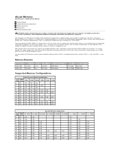
... computer uses 1066 MHz and 1333Mhz DDR3 unbuffered or registered ECC SDRAM memory. This supply voltage works well with a promise of a power consumption reduction of maximum 16 gigabyte in size. About Memory Dell Precision™ T5500 Service Manual Memory Modules Supported Memory Configurations Memory Subsystem Memory Slots Memory Population Rules WARNING: Before working inside your computer, read the safety information...
... computer uses 1066 MHz and 1333Mhz DDR3 unbuffered or registered ECC SDRAM memory. This supply voltage works well with a promise of a power consumption reduction of maximum 16 gigabyte in size. About Memory Dell Precision™ T5500 Service Manual Memory Modules Supported Memory Configurations Memory Subsystem Memory Slots Memory Population Rules WARNING: Before working inside your computer, read the safety information...
Service Manual
Page 3
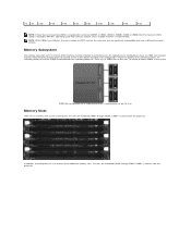
... the processor. All single-processor configurations have a different key notch location. Memory Slots There are six memory slots on the system board. In addition, the dual-processor riser features three additional memory slots. DIMM slot configuration for a single processor or a second processor on...an optional riser card that contains the secondary processor and the DIMMs associated with the secondary processor. There are numbered DIMM1 through DIMM3. Memory Subsystem The memory subsystem consists of twelve DIMMs in the system. 72 DR 8 GB 8 GB 8 GB 8 GB 8 GB 8 GB 8 ...
... the processor. All single-processor configurations have a different key notch location. Memory Slots There are six memory slots on the system board. In addition, the dual-processor riser features three additional memory slots. DIMM slot configuration for a single processor or a second processor on...an optional riser card that contains the secondary processor and the DIMMs associated with the secondary processor. There are numbered DIMM1 through DIMM3. Memory Subsystem The memory subsystem consists of twelve DIMMs in the system. 72 DR 8 GB 8 GB 8 GB 8 GB 8 GB 8 GB 8 ...

Service Manual
Page 4
For example, for a 4GB configuration consisting of mixed sizes, populate the larger DIMMs first. Memory Population Rules Your computer requires DIMMs within a configuration should generally be spread across as many channels as possible before ...the same size, populate in the following order: MB_DIMM1, Riser_DIMM1, MB_DIMM2, Riser_DIMM2, MB_DIMM3, Riser_DIMM3, MB_DIMM4, MB_DIMM5, MB_DIMM6. To maximize available memory bandwidth, DIMMs within a channel to achieve this. The population guidelines below help to be populated farthest from the processor first. Dual CPU ...
For example, for a 4GB configuration consisting of mixed sizes, populate the larger DIMMs first. Memory Population Rules Your computer requires DIMMs within a configuration should generally be spread across as many channels as possible before ...the same size, populate in the following order: MB_DIMM1, Riser_DIMM1, MB_DIMM2, Riser_DIMM2, MB_DIMM3, Riser_DIMM3, MB_DIMM4, MB_DIMM5, MB_DIMM6. To maximize available memory bandwidth, DIMMs within a channel to achieve this. The population guidelines below help to be populated farthest from the processor first. Dual CPU ...
Service Manual
Page 5
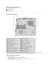
...system board. 3. For additional safety best practices information, see the Regulatory Compliance Homepage at www.dell.com/regulatory_compliance. About Your System Board Dell Precision™ T5500 Service Manual System Board Schematic Clearing Forgotten Passwords Clearing CMOS Settings System Board Schematic 1 Main Power... Front Fan Connector (FAN_FRONT) 7 Chassis Intrusion Header (INTRUDER) 21 Card Cage Fan (FAN_CCAG) 8 PCI-X Card Slot (SLOT6) 22 Memory Module Connectors (DIMM1-6) 9 PCI Card Slot (SLOT5) 23 Optional Serial/PS2 Connector (SERIAL2) 10 PCI Express 2.0 x16 Card Slot (SLOT4...
...system board. 3. For additional safety best practices information, see the Regulatory Compliance Homepage at www.dell.com/regulatory_compliance. About Your System Board Dell Precision™ T5500 Service Manual System Board Schematic Clearing Forgotten Passwords Clearing CMOS Settings System Board Schematic 1 Main Power... Front Fan Connector (FAN_FRONT) 7 Chassis Intrusion Header (INTRUDER) 21 Card Cage Fan (FAN_CCAG) 8 PCI-X Card Slot (SLOT6) 22 Memory Module Connectors (DIMM1-6) 9 PCI Card Slot (SLOT5) 23 Optional Serial/PS2 Connector (SERIAL2) 10 PCI Express 2.0 x16 Card Slot (SLOT4...
Service Manual
Page 10
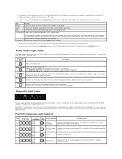
... test by changing the test settings. 4. Off 3- Off 4- The normal operating condition after POST is for running the Dell Diagnostics from system setup, memory, and various internal tests, and it is in your computer. Help Describes the test and may not display the names... of a functioning machine. Blinking Green System is fine. Off 2- Parameters The Dell Diagnostics obtains configuration information for further information. When...
... test by changing the test settings. 4. Off 3- Off 4- The normal operating condition after POST is for running the Dell Diagnostics from system setup, memory, and various internal tests, and it is in your computer. Help Describes the test and may not display the names... of a functioning machine. Blinking Green System is fine. Off 2- Parameters The Dell Diagnostics obtains configuration information for further information. When...
Service Manual
Page 11
... 1- Off 4- Blink 1- Off 1- BIOS not execution. Off 3- Off 2- Solid 4- Blink 4- Off 1- to the system. 1- Solid MEM Memory Memory subsystem configuration activity is now in progress or PCI device failure was detected and the system is in component such as CPU, VRM, PSU, or...asserted, SYS_PWRGOOD de-asserted) Mismatch Hardware detected a population incompatibility with a critical system component such as VRM, Video Riser, or Memory Riser. Off 3- Off OFF OFF Power light Off. System has successfully booted and is not green, see Pre-POST Diagnostic...
... 1- Off 4- Blink 1- Off 1- BIOS not execution. Off 3- Off 2- Solid 4- Blink 4- Off 1- to the system. 1- Solid MEM Memory Memory subsystem configuration activity is now in progress or PCI device failure was detected and the system is in component such as CPU, VRM, PSU, or...asserted, SYS_PWRGOOD de-asserted) Mismatch Hardware detected a population incompatibility with a critical system component such as VRM, Video Riser, or Memory Riser. Off 3- Off OFF OFF Power light Off. System has successfully booted and is not green, see Pre-POST Diagnostic...
Service Manual
Page 12
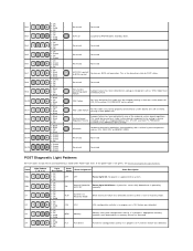
... Screen retrace tests test in progress. Solid 1- Off 1- Solid 3- Solid 1- Off 1- Solid 1- Solid 1- Solid 3- No memory modules were detected. PRV Other pre-video activity Indicates routine system activity preceding video initialization. Once the hand-off to video initialization.... bit 0 3-4-3 Search for video ROM in progress or USB subsystem failure. Solid 2- Off 1- Solid 2- Solid 3- Solid 3- Solid 2- MEM Memory Memory subsystem configuration activity is in progress or failure 2-1-1 1st 64 K RAM chip or data line failure - Solid 3- Off 4- Solid 4- Off 2-...
... Screen retrace tests test in progress. Solid 1- Off 1- Solid 3- Solid 1- Off 1- Solid 1- Solid 1- Solid 3- No memory modules were detected. PRV Other pre-video activity Indicates routine system activity preceding video initialization. Once the hand-off to video initialization.... bit 0 3-4-3 Search for video ROM in progress or USB subsystem failure. Solid 2- Off 1- Solid 2- Solid 3- Solid 3- Solid 2- MEM Memory Memory subsystem configuration activity is in progress or failure 2-1-1 1st 64 K RAM chip or data line failure - Solid 3- Off 4- Solid 4- Off 2-...
Service Manual
Page 13
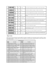
... - bit 4 2-2-2 1st 64 K RAM chip or data line failure - bit D 4-2-4 4-3-1 4-3-2 4-3-3 4-3-4 4-4-1 4-4-4 Unexpected interrupt in Protected Mode RAM test in progress or failure above address 0FFFFh No memory in Bank 0 Interval Timer Channel 2 test in progress or failure Time-Of-Day Clock test in progress or failure Super I/O chip failure Cache test failure...
... - bit 4 2-2-2 1st 64 K RAM chip or data line failure - bit D 4-2-4 4-3-1 4-3-2 4-3-3 4-3-4 4-4-1 4-4-4 Unexpected interrupt in Protected Mode RAM test in progress or failure above address 0FFFFh No memory in Bank 0 Interval Timer Channel 2 test in progress or failure Time-Of-Day Clock test in progress or failure Super I/O chip failure Cache test failure...
Service Manual
Page 14
Adding and Replacing Parts Dell Precision™ T5500 Service Manual Cover Battery Drives Bezel Hard Drive Tray Front Fan Assembly Memory Card Reader Memory Dual Processor Riser (Optional) System Board I/O Data Cable Chassis Intrusion Switch Front Bezel Hard Drive Floppy Drive Optical Drive Expansion Cards Heat Sink and Processor Power Supply
Adding and Replacing Parts Dell Precision™ T5500 Service Manual Cover Battery Drives Bezel Hard Drive Tray Front Fan Assembly Memory Card Reader Memory Dual Processor Riser (Optional) System Board I/O Data Cable Chassis Intrusion Switch Front Bezel Hard Drive Floppy Drive Optical Drive Expansion Cards Heat Sink and Processor Power Supply
Service Manual
Page 15
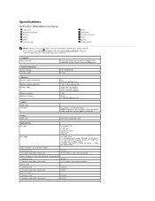
...; Processor 5500 series Quad-Core Intel® Xeon® Processor 5500 series Intel 5500/5520 64 bits Memory Memory module connectors Memory module capacities Memory type Minimum memory Maximum memory Video Video type: Discrete Audio Audio type Six Nine with optional riser 1 GB, 2 GB, 4 ... bits One PCI-X slot Connector pins Connector data width (maximum) 188 pins 64 bits Specifications Dell Precision™ T5500/T5500n Service Manual Processors System Information Memory Video Audio Expansion Bus Drives Connectors Controls and Lights Power Physical Environmental NOTE: Offerings may vary ...
...; Processor 5500 series Quad-Core Intel® Xeon® Processor 5500 series Intel 5500/5520 64 bits Memory Memory module connectors Memory module capacities Memory type Minimum memory Maximum memory Video Video type: Discrete Audio Audio type Six Nine with optional riser 1 GB, 2 GB, 4 ... bits One PCI-X slot Connector pins Connector data width (maximum) 188 pins 64 bits Specifications Dell Precision™ T5500/T5500n Service Manual Processors System Information Memory Video Audio Expansion Bus Drives Connectors Controls and Lights Power Physical Environmental NOTE: Offerings may vary ...
Service Manual
Page 16
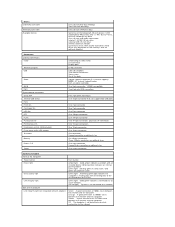
... fan Card cage fan HDD fan PCI PCI-X PCI Express x8 PCI Express x16 Front panel control (USB included) Front panel audio HDA header Processor Memory Power 12 V Power (Depending on video card) DVI connector Display port RJ-45 connector USB 2.0 compliant Two internal connectors Two in front Six at 1000Mbs...
... fan Card cage fan HDD fan PCI PCI-X PCI Express x8 PCI Express x16 Front panel control (USB included) Front panel audio HDA header Processor Memory Power 12 V Power (Depending on video card) DVI connector Display port RJ-45 connector USB 2.0 compliant Two internal connectors Two in front Six at 1000Mbs...
Service Manual
Page 28
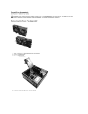
Front Fan Assembly Dell Precision™ T5500 Service Manual WARNING: Before working inside your computer, read the safety information that shipped with your computer. Follow the procedures in Before Working Inside Your Computer. 2. Removing the Front Fan Assembly 1. Remove the memory shroud. 5. Remove the computer cover. 3. Open the hard drive tray. 4. Disconnect the two fan cables from the system board. For additional safety best practices information, see the Regulatory Compliance Homepage at www.dell.com/regulatory_compliance.
Front Fan Assembly Dell Precision™ T5500 Service Manual WARNING: Before working inside your computer, read the safety information that shipped with your computer. Follow the procedures in Before Working Inside Your Computer. 2. Removing the Front Fan Assembly 1. Remove the memory shroud. 5. Remove the computer cover. 3. Open the hard drive tray. 4. Disconnect the two fan cables from the system board. For additional safety best practices information, see the Regulatory Compliance Homepage at www.dell.com/regulatory_compliance.
Service Manual
Page 43
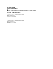
Remove the computer cover. 3. Disconnect the I/O data cable from the I /O Data Cable 1. Replacing the I /O panel. Remove the memory module shroud. 5. Removing the I /O Data Cable Dell Precision™ T5500 Service Manual WARNING: Before working inside your computer, read the safety information that shipped with your computer. Raise the hard drive tray. 4. Remove the computer ...
Remove the computer cover. 3. Disconnect the I/O data cable from the I /O Data Cable 1. Replacing the I /O panel. Remove the memory module shroud. 5. Removing the I /O Data Cable Dell Precision™ T5500 Service Manual WARNING: Before working inside your computer, read the safety information that shipped with your computer. Raise the hard drive tray. 4. Remove the computer ...
Service Manual
Page 44
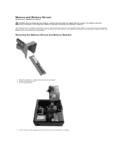
Memory and Memory Shroud Dell Precision™ T5500 Service Manual WARNING: Before working inside your computer, read the safety information that shipped with your computer. Memory modules are illustrated below. Lift the hard drive tray. 4. For additional safety best practices information, see Dual Processor Riser (Optional)). Remove the computer cover. 3. Removing the Memory Shroud and Memory Modules 1. Lift the...
Memory and Memory Shroud Dell Precision™ T5500 Service Manual WARNING: Before working inside your computer, read the safety information that shipped with your computer. Memory modules are illustrated below. Lift the hard drive tray. 4. For additional safety best practices information, see Dual Processor Riser (Optional)). Remove the computer cover. 3. Removing the Memory Shroud and Memory Modules 1. Lift the...

Service Manual
Page 45
Using your thumbs, gently push down on the memory module retention clips to release the module from the connector on the system board. 6. Lift the first memory module straight up and out of the computer, and repeat for any remaining memory modules. 5.
Using your thumbs, gently push down on the memory module retention clips to release the module from the connector on the system board. 6. Lift the first memory module straight up and out of the computer, and repeat for any remaining memory modules. 5.
Service Manual
Page 47
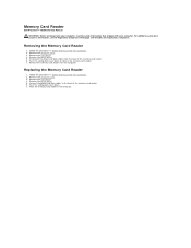
Memory Card Reader Dell Precision™ T5500 Service Manual WARNING: Before working inside your computer, read the safety information that shipped with your computer. Push the sliding plate lever down to the back of the memory card reader. 6. Remove the computer cover. 3. Remove the computer cover. 3. Remove the drives bezel. 5. Follow the procedures in the computer...
Memory Card Reader Dell Precision™ T5500 Service Manual WARNING: Before working inside your computer, read the safety information that shipped with your computer. Push the sliding plate lever down to the back of the memory card reader. 6. Remove the computer cover. 3. Remove the computer cover. 3. Remove the drives bezel. 5. Follow the procedures in the computer...

Service Manual
Page 59
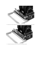
While pressing on the memory module release tabs to release the first dual processor memory module from the dual processor assembly. 9. 8. Gently press down on the blue release tab, remove the dual processor fan assembly from the connector.
While pressing on the memory module release tabs to release the first dual processor memory module from the dual processor assembly. 9. 8. Gently press down on the blue release tab, remove the dual processor fan assembly from the connector.
Service Manual
Page 60
10. Remove the first memory module from the dual processor board. Disconnect the dual processor heat sink fan cable from the dual processor board, and repeat with any remaining memory modules. 11.
10. Remove the first memory module from the dual processor board. Disconnect the dual processor heat sink fan cable from the dual processor board, and repeat with any remaining memory modules. 11.
Service Manual
Page 69
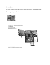
... safety best practices information, see the Regulatory Compliance Homepage at www.dell.com/regulatory_compliance. Remove the computer cover. 3. Remove any memory modules. 9. Remove the front fan assembly. 6. Remove the memory shroud. 5. Remove any expansion or video cards and raise the ...expansion card retention arm. 7. Disconnect the front panel audio cable from the system board. Follow the procedures in Before Working Inside Your Computer. 2. System Board Dell Precision™ T5500 Service Manual...
... safety best practices information, see the Regulatory Compliance Homepage at www.dell.com/regulatory_compliance. Remove the computer cover. 3. Remove any memory modules. 9. Remove the front fan assembly. 6. Remove the memory shroud. 5. Remove any expansion or video cards and raise the ...expansion card retention arm. 7. Disconnect the front panel audio cable from the system board. Follow the procedures in Before Working Inside Your Computer. 2. System Board Dell Precision™ T5500 Service Manual...


