Setup and Features Information Tech Sheet
Page 1
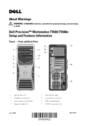
Front and Back View 12 17 1 11 13 14 2 10 3 9 4 16 5 8 6 7 15 1 optical drives (2) 3 headphone connector 5 power button, power light 7 diagnostic lights (4) June 2009 2 link integrity light 4 microphone connector 6 Dell rotatable badge 8 USB 2.0 connectors (2) Model: DCTA About Warnings WARNING: A WARNING indicates a potential for property damage, personal injury, or death. Dell Precision™ Workstation T5500/T5500n Setup and Features Information Tower -
Front and Back View 12 17 1 11 13 14 2 10 3 9 4 16 5 8 6 7 15 1 optical drives (2) 3 headphone connector 5 power button, power light 7 diagnostic lights (4) June 2009 2 link integrity light 4 microphone connector 6 Dell rotatable badge 8 USB 2.0 connectors (2) Model: DCTA About Warnings WARNING: A WARNING indicates a potential for property damage, personal injury, or death. Dell Precision™ Workstation T5500/T5500n Setup and Features Information Tower -
Setup and Features Information Tech Sheet
Page 2
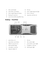
Front View 1 2 34 567 11 10 9 8 1 optical drives (2) 3 optical drive eject button 5 USB 2.0 connectors (2) 7 Dell rotatable badge 9 microphone connector 11 diagnostic lights (4) 2 flex bay 4 drive activity light 6 power button, power light 8 headphone connector 10 link integrity light 9 drive activity light 10 flex bay 11 optical drive eject button 12 power supply diagnostic light 13 power supply diagnostic button 14 power connector 15 back panel connectors 16 expansion card slots (6) 17 cover-release latch and padlock ring Desktop -
Front View 1 2 34 567 11 10 9 8 1 optical drives (2) 3 optical drive eject button 5 USB 2.0 connectors (2) 7 Dell rotatable badge 9 microphone connector 11 diagnostic lights (4) 2 flex bay 4 drive activity light 6 power button, power light 8 headphone connector 10 link integrity light 9 drive activity light 10 flex bay 11 optical drive eject button 12 power supply diagnostic light 13 power supply diagnostic button 14 power connector 15 back panel connectors 16 expansion card slots (6) 17 cover-release latch and padlock ring Desktop -
Setup and Features Information Tech Sheet
Page 3
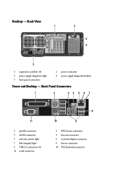
Back Panel Connectors 1 2 34 5 67 11 1 parallel connector 3 eSATA connector 5 network activity light 7 link integrity light 9 USB 2.0 connectors (6) 11 serial connector 8 10 9 2 PS/2 mouse connector 4 line-out connector 6 network adapter connector 8 line-in connector 10 PS/2 keyboard connector Desktop - Back View 1 2 3 4 5 1 expansion card slots (6) 3 power supply diagnostic light 5 back panel connectors 2 power connector 4 power supply diagnostic button Tower and Desktop -
Back Panel Connectors 1 2 34 5 67 11 1 parallel connector 3 eSATA connector 5 network activity light 7 link integrity light 9 USB 2.0 connectors (6) 11 serial connector 8 10 9 2 PS/2 mouse connector 4 line-out connector 6 network adapter connector 8 line-in connector 10 PS/2 keyboard connector Desktop - Back View 1 2 3 4 5 1 expansion card slots (6) 3 power supply diagnostic light 5 back panel connectors 2 power connector 4 power supply diagnostic button Tower and Desktop -
Setup and Features Information Tech Sheet
Page 8
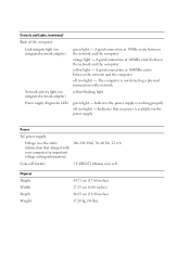
... no power is working properly off (no light) - A good connection at 100Mbs exists between the network and the computer orange light - A good connection at 10Mbs exists between the network and the computer yellow light - Indicates the power supply is available for... (38 lbs) The computer is not detecting a physical connection to the network Network activity light (on integrated network adapter) green light - Controls and Lights (continued) Back of the computer: Link integrity light (on integrated network adapter) yellow blinking light Power supply diagnostic LED green...
... no power is working properly off (no light) - A good connection at 100Mbs exists between the network and the computer orange light - A good connection at 10Mbs exists between the network and the computer yellow light - Indicates the power supply is available for... (38 lbs) The computer is not detecting a physical connection to the network Network activity light (on integrated network adapter) green light - Controls and Lights (continued) Back of the computer: Link integrity light (on integrated network adapter) yellow blinking light Power supply diagnostic LED green...
Service Manual
Page 7
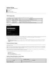
... you cannot change settings that option. This feature offers a quick and convenient method with previous Dell Precision™ workstation platforms, your computer includes a one-time boot menu. If you can change...lights first flash. System setup key functions are listed at the Dell™ Logo screen. and right-arrow keys, or +/- < > The upper-right corner of the screen. l Diagnostics options-The boot menu includes two diagnostic options, IDE Drive Diagnostics (90/90 Hard Drive Diagnostics) and Boot to the user-definable settings. System Setup Dell Precision™ T5500...
... you cannot change settings that option. This feature offers a quick and convenient method with previous Dell Precision™ workstation platforms, your computer includes a one-time boot menu. If you can change...lights first flash. System setup key functions are listed at the Dell™ Logo screen. and right-arrow keys, or +/- < > The upper-right corner of the screen. l Diagnostics options-The boot menu includes two diagnostic options, IDE Drive Diagnostics (90/90 Hard Drive Diagnostics) and Boot to the user-definable settings. System Setup Dell Precision™ T5500...
Service Manual
Page 9
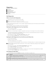
... see the Microsoft® Windows® desktop. Run Express Test first to increase the possibility of devices. Diagnostics Dell Precision™ T5500 Service Manual Dell Diagnostics Power Button Light Codes Diagnostic Light Codes Pre-POST Diagnostic Light Patterns POST Diagnostic Light Patterns Beep Codes Dell Diagnostics When to Use the Dell Diagnostics It is recommended that you print these procedures before you want to run. Turn on...
... see the Microsoft® Windows® desktop. Run Express Test first to increase the possibility of devices. Diagnostics Dell Precision™ T5500 Service Manual Dell Diagnostics Power Button Light Codes Diagnostic Light Codes Pre-POST Diagnostic Light Patterns POST Diagnostic Light Patterns Beep Codes Dell Diagnostics When to Use the Dell Diagnostics It is recommended that you print these procedures before you want to run. Turn on...
Service Manual
Page 10
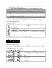
... 4- ACPI S1 Windows Standby State. The device list may indicate requirements for the selected device. To exit the Dell Diagnostics and restart the computer, close the Main Menu screen. Power Button Light Codes The diagnostic lights give much more information. Description Blinking Amber Initial state of all devices attached to determine which state the system...
... 4- ACPI S1 Windows Standby State. The device list may indicate requirements for the selected device. To exit the Dell Diagnostics and restart the computer, close the Main Menu screen. Power Button Light Codes The diagnostic lights give much more information. Description Blinking Amber Initial state of all devices attached to determine which state the system...
Service Manual
Page 11
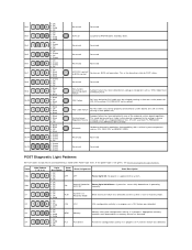
...Off 2- Off 2- Blink 1- Off 4- Blink 1- Off 1- Off 3- Blink 1- Off 4- BIOS not execution. This is not green, see Pre-POST Diagnostic Light Patterns. This could be crimped creating a short on a regulated power rail. (PS_ON asserted, PS_PWRGOOD asserted, SYS_PWRGOOD de-asserted) Mismatch Hardware detected a population ...PSU cable may not be properly connected to RAM Windows Standby State. Reserved Reserved Reserved Reserved POST Diagnostic Light Patterns All POST codes except S0 are accompanied by a plug-in one of the onboard system board regulators. Off 4- ...
...Off 2- Off 2- Blink 1- Off 4- Blink 1- Off 1- Off 3- Blink 1- Off 4- BIOS not execution. This is not green, see Pre-POST Diagnostic Light Patterns. This could be crimped creating a short on a regulated power rail. (PS_ON asserted, PS_PWRGOOD asserted, SYS_PWRGOOD de-asserted) Mismatch Hardware detected a population ...PSU cable may not be properly connected to RAM Windows Standby State. Reserved Reserved Reserved Reserved POST Diagnostic Light Patterns All POST codes except S0 are accompanied by a plug-in one of the onboard system board regulators. Off 4- ...


