Service Manual
Page 1
... and trade names may be used in this text: Dell, the DELL logo, and Dell Precision are trademarks of this material in the United States and/or other than its own. Dell Precision™ T5500 Service Manual Working on Your Computer Adding and Replacing Parts Specifications Diagnostics About Memory About Your System Board System Setup Notes, Cautions, and...
... and trade names may be used in this text: Dell, the DELL logo, and Dell Precision are trademarks of this material in the United States and/or other than its own. Dell Precision™ T5500 Service Manual Working on Your Computer Adding and Replacing Parts Specifications Diagnostics About Memory About Your System Board System Setup Notes, Cautions, and...
Service Manual
Page 2
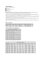
... the higher bandwidth made possible by DDR3's 8 bit deep prefetch buffer, whereas DDR2's is 4 bits, and DDR's is a random access memory technology. About Memory Dell Precision™ T5500 Service Manual Memory Modules Supported Memory Configurations Memory Subsystem Memory Slots Memory Population Rules WARNING: Before working inside your computer, read the safety information that shipped with a promise of a power consumption reduction...
... the higher bandwidth made possible by DDR3's 8 bit deep prefetch buffer, whereas DDR2's is 4 bits, and DDR's is a random access memory technology. About Memory Dell Precision™ T5500 Service Manual Memory Modules Supported Memory Configurations Memory Subsystem Memory Slots Memory Population Rules WARNING: Before working inside your computer, read the safety information that shipped with a promise of a power consumption reduction...
Service Manual
Page 3
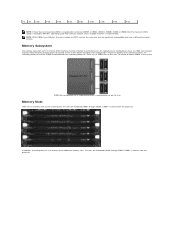
...second processor on the system board. In addition, the dual-processor riser features three additional memory slots. Memory Subsystem The memory subsystem consists of twelve DIMMs in the system. Memory Slots There are numbered DIMM1 through DIMM6. DIMM1 is reduced to the primary processor located... DIMM4, DIMM2 & DIMM5, DIMM3 & DIMM6) then the maximum DDR3 speed is furthest from the processor. Spreading Quad Rank memory modules across multiple channels is furthest from the processor. Dual-processor configurations require an optional riser card that contains the secondary processor...
...second processor on the system board. In addition, the dual-processor riser features three additional memory slots. Memory Subsystem The memory subsystem consists of twelve DIMMs in the system. Memory Slots There are numbered DIMM1 through DIMM6. DIMM1 is reduced to the primary processor located... DIMM4, DIMM2 & DIMM5, DIMM3 & DIMM6) then the maximum DDR3 speed is furthest from the processor. Spreading Quad Rank memory modules across multiple channels is furthest from the processor. Dual-processor configurations require an optional riser card that contains the secondary processor...

Service Manual
Page 4
...configuration contains DIMMs of one 2GB DIMM and two 1GB DIMMs, the population would be populated farthest from the processor first. To maximize available memory bandwidth, DIMMs within a channel to achieve this. In addition, when populating a Quad-rank DIMM with the DIMMs farthest from the CPU...in the same channel, the Quad-rank DIMM must be DIMM1=2GB, DIMM2=1GB, DIMM3=1GB, DIMM4=empty, DIMM5=empty, DIMM6=empty. Memory Population Rules Your computer requires DIMMs within a configuration should generally be spread across as many channels as possible before DIMM slots 4, 5 and ...
...configuration contains DIMMs of one 2GB DIMM and two 1GB DIMMs, the population would be populated farthest from the processor first. To maximize available memory bandwidth, DIMMs within a channel to achieve this. In addition, when populating a Quad-rank DIMM with the DIMMs farthest from the CPU...in the same channel, the Quad-rank DIMM must be DIMM1=2GB, DIMM2=1GB, DIMM3=1GB, DIMM4=empty, DIMM5=empty, DIMM6=empty. Memory Population Rules Your computer requires DIMMs within a configuration should generally be spread across as many channels as possible before DIMM slots 4, 5 and ...
Service Manual
Page 5
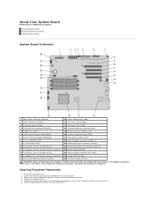
Clearing Forgotten Passwords 1. About Your System Board Dell Precision™ T5500 Service Manual System Board Schematic Clearing Forgotten Passwords Clearing CMOS Settings System Board Schematic 1 Main Power Connector (POWER1) 15 Type A USB Port (...Front Panel Connector (FRONTPANEL) 20 Front Fan Connector (FAN_FRONT) 7 Chassis Intrusion Header (INTRUDER) 21 Card Cage Fan (FAN_CCAG) 8 PCI-X Card Slot (SLOT6) 22 Memory Module Connectors (DIMM1-6) 9 PCI Card Slot (SLOT5) 23 Optional Serial/PS2 Connector (SERIAL2) 10 PCI Express 2.0 x16 Card Slot (SLOT4) 24 Auxiliary Hard-drive ...
Clearing Forgotten Passwords 1. About Your System Board Dell Precision™ T5500 Service Manual System Board Schematic Clearing Forgotten Passwords Clearing CMOS Settings System Board Schematic 1 Main Power Connector (POWER1) 15 Type A USB Port (...Front Panel Connector (FRONTPANEL) 20 Front Fan Connector (FAN_FRONT) 7 Chassis Intrusion Header (INTRUDER) 21 Card Cage Fan (FAN_CCAG) 8 PCI-X Card Slot (SLOT6) 22 Memory Module Connectors (DIMM1-6) 9 PCI Card Slot (SLOT5) 23 Optional Serial/PS2 Connector (SERIAL2) 10 PCI Express 2.0 x16 Card Slot (SLOT4) 24 Auxiliary Hard-drive ...
Service Manual
Page 10
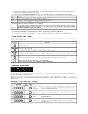
...Pb0a Pb0b Pb0c Pb1 Light Pattern ( 1 2 3 4 ) Light Description 1- Off 2- Off 3- Normal System is blank. To exit the Dell Diagnostics and restart the computer, close the Main Menu screen. Description Blinking Amber Initial state of all devices attached to your computer. Off 2- 2.... device. If a problem is for all four lights to the Main Menu screen. Parameters The Dell Diagnostics obtains configuration information for all devices from system setup, memory, and various internal tests, and it has started fetching opcodes. The normal operating condition after POST...
...Pb0a Pb0b Pb0c Pb1 Light Pattern ( 1 2 3 4 ) Light Description 1- Off 2- Off 3- Normal System is blank. To exit the Dell Diagnostics and restart the computer, close the Main Menu screen. Description Blinking Amber Initial state of all devices attached to your computer. Off 2- 2.... device. If a problem is for all four lights to the Main Menu screen. Parameters The Dell Diagnostics obtains configuration information for all devices from system setup, memory, and various internal tests, and it has started fetching opcodes. The normal operating condition after POST...
Service Manual
Page 11
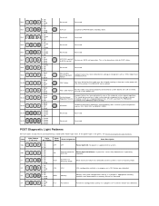
...Off 3- Off 2- Off 4- Off 3- Off CPU CPU CPU configuration activity is in progress or a CPU failure was detected. 1- Solid MEM Memory Memory subsystem configuration activity is in progress. Off 3- Green 3- Green 4- Blink 4- Off 4- Off 4- Blink 2- Blink 2- Blink 4- Off ... see Pre-POST Diagnostic Light Patterns. Off 2- Off 2- Green 3- Green 2- Off 3- Blink 1- Off 4- Appropriate memory modules were detected but a memory failure has occurred. 1- Solid 1- Off 1- Off 3- to BIOS control Reserved Reserved Non-System board Regulator Failure A ...
...Off 3- Off 2- Off 4- Off 3- Off CPU CPU CPU configuration activity is in progress or a CPU failure was detected. 1- Solid MEM Memory Memory subsystem configuration activity is in progress. Off 3- Green 3- Green 4- Blink 4- Off 4- Off 4- Blink 2- Blink 2- Blink 4- Off ... see Pre-POST Diagnostic Light Patterns. Off 2- Off 2- Green 3- Green 2- Off 3- Blink 1- Off 4- Appropriate memory modules were detected but a memory failure has occurred. 1- Solid 1- Off 1- Off 3- to BIOS control Reserved Reserved Non-System board Regulator Failure A ...
Service Manual
Page 12
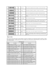
... 2- Off 1- Off 4- Off 3- Solid 3- Off 4- Solid 4- Solid 3- CFG Resource configuration System resource configuration in nonvolatile random-access memory (NVRAM). System Beep Codes Beep Code Description Beep Code Description 1-1-2 CPU register test in progress or failure 2-4-4 1st 64 K RAM chip or...for example, one beep followed by a second beep, then followed by a burst of POST process. No memory modules were detected. MEM Memory Memory subsystem configuration activity is done, the lights turn it back on, the BIOS is being considered to indicate the...
... 2- Off 1- Off 4- Off 3- Solid 3- Off 4- Solid 4- Solid 3- CFG Resource configuration System resource configuration in nonvolatile random-access memory (NVRAM). System Beep Codes Beep Code Description Beep Code Description 1-1-2 CPU register test in progress or failure 2-4-4 1st 64 K RAM chip or...for example, one beep followed by a second beep, then followed by a burst of POST process. No memory modules were detected. MEM Memory Memory subsystem configuration activity is done, the lights turn it back on, the BIOS is being considered to indicate the...
Service Manual
Page 13
... - bit B 2-4-1 1st 64 K RAM chip or data line failure - bit D 4-2-4 4-3-1 4-3-2 4-3-3 4-3-4 4-4-1 4-4-4 Unexpected interrupt in Protected Mode RAM test in progress or failure above address 0FFFFh No memory in Bank 0 Interval Timer Channel 2 test in progress or failure Time-Of-Day Clock test in progress or failure Super I/O chip failure Cache test failure...
... - bit B 2-4-1 1st 64 K RAM chip or data line failure - bit D 4-2-4 4-3-1 4-3-2 4-3-3 4-3-4 4-4-1 4-4-4 Unexpected interrupt in Protected Mode RAM test in progress or failure above address 0FFFFh No memory in Bank 0 Interval Timer Channel 2 test in progress or failure Time-Of-Day Clock test in progress or failure Super I/O chip failure Cache test failure...
Service Manual
Page 14
Adding and Replacing Parts Dell Precision™ T5500 Service Manual Cover Battery Drives Bezel Hard Drive Tray Front Fan Assembly Memory Card Reader Memory Dual Processor Riser (Optional) System Board I/O Data Cable Chassis Intrusion Switch Front Bezel Hard Drive Floppy Drive Optical Drive Expansion Cards Heat Sink and Processor Power Supply
Adding and Replacing Parts Dell Precision™ T5500 Service Manual Cover Battery Drives Bezel Hard Drive Tray Front Fan Assembly Memory Card Reader Memory Dual Processor Riser (Optional) System Board I/O Data Cable Chassis Intrusion Switch Front Bezel Hard Drive Floppy Drive Optical Drive Expansion Cards Heat Sink and Processor Power Supply
Service Manual
Page 15
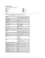
...; Processor 5500 series Quad-Core Intel® Xeon® Processor 5500 series Intel 5500/5520 64 bits Memory Memory module connectors Memory module capacities Memory type Minimum memory Maximum memory Video Video type: Discrete Audio Audio type Six Nine with optional riser 1 GB, 2 GB, 4...and Support, and then select the option to view information about your Tablet-PC. Specifications Dell Precision™ T5500/T5500n Service Manual Processors System Information Memory Video Audio Expansion Bus Drives Connectors Controls and Lights Power Physical Environmental NOTE: Offerings may vary...
...; Processor 5500 series Quad-Core Intel® Xeon® Processor 5500 series Intel 5500/5520 64 bits Memory Memory module connectors Memory module capacities Memory type Minimum memory Maximum memory Video Video type: Discrete Audio Audio type Six Nine with optional riser 1 GB, 2 GB, 4...and Support, and then select the option to view information about your Tablet-PC. Specifications Dell Precision™ T5500/T5500n Service Manual Processors System Information Memory Video Audio Expansion Bus Drives Connectors Controls and Lights Power Physical Environmental NOTE: Offerings may vary...
Service Manual
Page 16
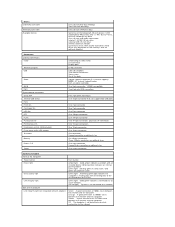
... fan Card cage fan HDD fan PCI PCI-X PCI Express x8 PCI Express x16 Front panel control (USB included) Front panel audio HDA header Processor Memory Power 12 V Power (Depending on integrated network adapter) Push button Amber light Solid amber indicates a problem with an installed device; solid green for power-on...
... fan Card cage fan HDD fan PCI PCI-X PCI Express x8 PCI Express x16 Front panel control (USB included) Front panel audio HDA header Processor Memory Power 12 V Power (Depending on integrated network adapter) Push button Amber light Solid amber indicates a problem with an installed device; solid green for power-on...
Service Manual
Page 28
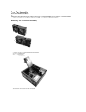
For additional safety best practices information, see the Regulatory Compliance Homepage at www.dell.com/regulatory_compliance. Remove the computer cover. 3. Remove the memory shroud. 5. Removing the Front Fan Assembly 1. Follow the procedures in Before Working Inside Your Computer. 2. Open the hard drive tray. 4. Disconnect the two fan cables from the system board. Front Fan Assembly Dell Precision™ T5500 Service Manual WARNING: Before working inside your computer, read the safety information that shipped with your computer.
For additional safety best practices information, see the Regulatory Compliance Homepage at www.dell.com/regulatory_compliance. Remove the computer cover. 3. Remove the memory shroud. 5. Removing the Front Fan Assembly 1. Follow the procedures in Before Working Inside Your Computer. 2. Open the hard drive tray. 4. Disconnect the two fan cables from the system board. Front Fan Assembly Dell Precision™ T5500 Service Manual WARNING: Before working inside your computer, read the safety information that shipped with your computer.
Service Manual
Page 43
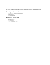
.... 6. Replacing the I /O panel. Connect the I/O data cable to the I /O Data Cable 1. Remove the memory module shroud. 5. Raise the hard drive tray. 4. Remove the computer cover. 3. Follow the procedures in Before Working Inside Your Computer. 2. I/O Data Cable Dell Precision™ T5500 Service Manual WARNING: Before working inside your computer, read the safety information that shipped...
.... 6. Replacing the I /O panel. Connect the I/O data cable to the I /O Data Cable 1. Remove the memory module shroud. 5. Raise the hard drive tray. 4. Remove the computer cover. 3. Follow the procedures in Before Working Inside Your Computer. 2. I/O Data Cable Dell Precision™ T5500 Service Manual WARNING: Before working inside your computer, read the safety information that shipped...
Service Manual
Page 44
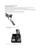
Memory and Memory Shroud Dell Precision™ T5500 Service Manual WARNING: Before working inside your computer, read the safety information that shipped with your computer. Follow the procedures in Before Working Inside Your Computer. 2. Your computer features an optional dual-processor riser to accommodate dual processor and expanded memory options (see the Regulatory Compliance Homepage at www...
Memory and Memory Shroud Dell Precision™ T5500 Service Manual WARNING: Before working inside your computer, read the safety information that shipped with your computer. Follow the procedures in Before Working Inside Your Computer. 2. Your computer features an optional dual-processor riser to accommodate dual processor and expanded memory options (see the Regulatory Compliance Homepage at www...

Service Manual
Page 45
Lift the first memory module straight up and out of the computer, and repeat for any remaining memory modules. 5. Using your thumbs, gently push down on the memory module retention clips to release the module from the connector on the system board. 6.
Lift the first memory module straight up and out of the computer, and repeat for any remaining memory modules. 5. Using your thumbs, gently push down on the memory module retention clips to release the module from the connector on the system board. 6.
Service Manual
Page 47
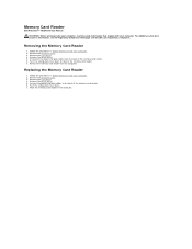
... the computer cover. 3. Remove the front bezel. 4. Disconnect the power and data cables from the computer. Connect the power and data cables to release the memory card reader. 7. Memory Card Reader Dell Precision™ T5500 Service Manual WARNING: Before working inside your computer, read the safety information that shipped with your computer. Removing the...
... the computer cover. 3. Remove the front bezel. 4. Disconnect the power and data cables from the computer. Connect the power and data cables to release the memory card reader. 7. Memory Card Reader Dell Precision™ T5500 Service Manual WARNING: Before working inside your computer, read the safety information that shipped with your computer. Removing the...

Service Manual
Page 59
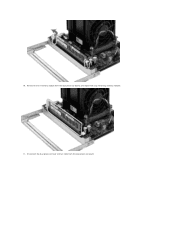
Gently press down on the blue release tab, remove the dual processor fan assembly from the connector. 8. While pressing on the memory module release tabs to release the first dual processor memory module from the dual processor assembly. 9.
Gently press down on the blue release tab, remove the dual processor fan assembly from the connector. 8. While pressing on the memory module release tabs to release the first dual processor memory module from the dual processor assembly. 9.
Service Manual
Page 60
10. Disconnect the dual processor heat sink fan cable from the dual processor board, and repeat with any remaining memory modules. 11. Remove the first memory module from the dual processor board.
10. Disconnect the dual processor heat sink fan cable from the dual processor board, and repeat with any remaining memory modules. 11. Remove the first memory module from the dual processor board.
Service Manual
Page 69
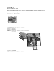
... from the system board. Remove the memory shroud. 5. Remove any memory modules. 9. For additional safety best practices information, see the Regulatory Compliance Homepage at www.dell.com/regulatory_compliance. Remove the computer cover. 3. Remove any expansion or video cards and raise the expansion card retention arm. 7. System Board Dell Precision™ T5500 Service Manual WARNING: Before working...
... from the system board. Remove the memory shroud. 5. Remove any memory modules. 9. For additional safety best practices information, see the Regulatory Compliance Homepage at www.dell.com/regulatory_compliance. Remove the computer cover. 3. Remove any expansion or video cards and raise the expansion card retention arm. 7. System Board Dell Precision™ T5500 Service Manual WARNING: Before working...


