Service Manual
Page 5
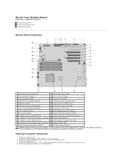
...6. Remove the 2-pin jumper plug from pins 3 and 4 and set the jumper plug aside. 4. About Your System Board Dell Precision™ T5500 Service Manual System Board Schematic Clearing Forgotten Passwords Clearing CMOS Settings System Board Schematic 1 Main Power Connector (POWER1) 15 Type A ... (CPU1) 5 Floppy Drive (DSKT) 19 Power Connector (POWER_CPU1) 6 Front Panel Connector (FRONTPANEL) 20 Front Fan Connector (FAN_FRONT) 7 Chassis Intrusion Header (INTRUDER) 21 Card Cage Fan (FAN_CCAG) 8 PCI-X Card Slot (SLOT6) 22 Memory Module Connectors (DIMM1-6) 9 PCI Card Slot (SLOT5)...
...6. Remove the 2-pin jumper plug from pins 3 and 4 and set the jumper plug aside. 4. About Your System Board Dell Precision™ T5500 Service Manual System Board Schematic Clearing Forgotten Passwords Clearing CMOS Settings System Board Schematic 1 Main Power Connector (POWER1) 15 Type A ... (CPU1) 5 Floppy Drive (DSKT) 19 Power Connector (POWER_CPU1) 6 Front Panel Connector (FRONTPANEL) 20 Front Fan Connector (FAN_FRONT) 7 Chassis Intrusion Header (INTRUDER) 21 Card Cage Fan (FAN_CCAG) 8 PCI-X Card Slot (SLOT6) 22 Memory Module Connectors (DIMM1-6) 9 PCI Card Slot (SLOT5)...
Service Manual
Page 14
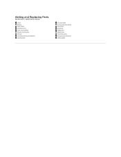
Adding and Replacing Parts Dell Precision™ T5500 Service Manual Cover Battery Drives Bezel Hard Drive Tray Front Fan Assembly Memory Card Reader Memory Dual Processor Riser (Optional) System Board I/O Data Cable Chassis Intrusion Switch Front Bezel Hard Drive Floppy Drive Optical Drive Expansion Cards Heat Sink and Processor Power Supply
Adding and Replacing Parts Dell Precision™ T5500 Service Manual Cover Battery Drives Bezel Hard Drive Tray Front Fan Assembly Memory Card Reader Memory Dual Processor Riser (Optional) System Board I/O Data Cable Chassis Intrusion Switch Front Bezel Hard Drive Floppy Drive Optical Drive Expansion Cards Heat Sink and Processor Power Supply
Service Manual
Page 16
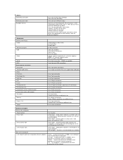
... a problem with an optional adapter) Connectors External connectors: Video Network adapter USB Audio Serial PS/2 System board connectors: Serial ATA Internal USB device Fans: Front fan Card cage fan HDD fan PCI PCI-X PCI Express x8 PCI Express x16 Front panel control (USB included) Front panel audio HDA header Processor Memory Power 12 V Power...
... a problem with an optional adapter) Connectors External connectors: Video Network adapter USB Audio Serial PS/2 System board connectors: Serial ATA Internal USB device Fans: Front fan Card cage fan HDD fan PCI PCI-X PCI Express x8 PCI Express x16 Front panel control (USB included) Front panel audio HDA header Processor Memory Power 12 V Power...
Service Manual
Page 28
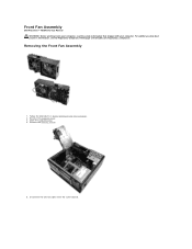
Remove the memory shroud. 5. Follow the procedures in Before Working Inside Your Computer. 2. Open the hard drive tray. 4. Disconnect the two fan cables from the system board. Removing the Front Fan Assembly 1. Remove the computer cover. 3. For additional safety best practices information, see the Regulatory Compliance Homepage at www.dell.com/regulatory_compliance. Front Fan Assembly Dell Precision™ T5500 Service Manual WARNING: Before working inside your computer, read the safety information that shipped with your computer.
Remove the memory shroud. 5. Follow the procedures in Before Working Inside Your Computer. 2. Open the hard drive tray. 4. Disconnect the two fan cables from the system board. Removing the Front Fan Assembly 1. Remove the computer cover. 3. For additional safety best practices information, see the Regulatory Compliance Homepage at www.dell.com/regulatory_compliance. Front Fan Assembly Dell Precision™ T5500 Service Manual WARNING: Before working inside your computer, read the safety information that shipped with your computer.

Service Manual
Page 29
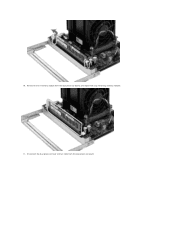
Remove the screw that secures the front fan assembly. 7. Remove the fan assembly from the computer 6.
Remove the screw that secures the front fan assembly. 7. Remove the fan assembly from the computer 6.
Service Manual
Page 43
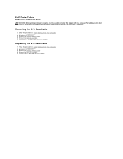
... front fan assembly. 6. Connect the I/O data cable to the I /O panel. Replacing the I /O Data Cable 1. Remove the memory module shroud. 5. Removing the I /O Data Cable 1. Remove the computer cover. 3. For additional safety best practices information, see the Regulatory Compliance Homepage at www.dell.com/regulatory_compliance. Remove the memory module shroud. 5. I/O Data Cable Dell Precision™ T5500 Service...
... front fan assembly. 6. Connect the I/O data cable to the I /O panel. Replacing the I /O Data Cable 1. Remove the memory module shroud. 5. Removing the I /O Data Cable 1. Remove the computer cover. 3. For additional safety best practices information, see the Regulatory Compliance Homepage at www.dell.com/regulatory_compliance. Remove the memory module shroud. 5. I/O Data Cable Dell Precision™ T5500 Service...

Service Manual
Page 58
Disconnect the dual processor fan cable from the computer. 7. Remove the dual processor riser completely from the dual processor board. 6.
Disconnect the dual processor fan cable from the computer. 7. Remove the dual processor riser completely from the dual processor board. 6.

Service Manual
Page 59
8. Gently press down on the blue release tab, remove the dual processor fan assembly from the connector. While pressing on the memory module release tabs to release the first dual processor memory module from the dual processor assembly. 9.
8. Gently press down on the blue release tab, remove the dual processor fan assembly from the connector. While pressing on the memory module release tabs to release the first dual processor memory module from the dual processor assembly. 9.
Service Manual
Page 60
Remove the first memory module from the dual processor board. 10. Disconnect the dual processor heat sink fan cable from the dual processor board, and repeat with any remaining memory modules. 11.
Remove the first memory module from the dual processor board. 10. Disconnect the dual processor heat sink fan cable from the dual processor board, and repeat with any remaining memory modules. 11.

Service Manual
Page 61
Remove the dual processor heat sink fan assembly from the dual processor riser board. 12. Loosen the four captive screws on the dual processor heat sink/fan assembly. 13.
Remove the dual processor heat sink fan assembly from the dual processor riser board. 12. Loosen the four captive screws on the dual processor heat sink/fan assembly. 13.
Service Manual
Page 69
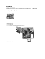
System Board Dell Precision™ T5500 Service Manual WARNING: Before working inside your computer, read the safety information that shipped with your computer. For additional safety best practices information, see the Regulatory Compliance Homepage at www.dell.com/regulatory_compliance. Follow the procedures in Before ...Working Inside Your Computer. 2. Lift the hard drive tray. 4. Remove the memory shroud. 5. Disconnect the front panel audio cable from the system board. Remove the front fan assembly. 6. ...
System Board Dell Precision™ T5500 Service Manual WARNING: Before working inside your computer, read the safety information that shipped with your computer. For additional safety best practices information, see the Regulatory Compliance Homepage at www.dell.com/regulatory_compliance. Follow the procedures in Before ...Working Inside Your Computer. 2. Lift the hard drive tray. 4. Remove the memory shroud. 5. Disconnect the front panel audio cable from the system board. Remove the front fan assembly. 6. ...


